Electric actuation of valve based on knowledge of closing time of valve

A technology of closing time and electric operation, which is applied in electrical control, engine control, fuel injection control, etc., can solve the problem of not being able to determine the exact timing of injection valve or injector closing, and achieve the requirement of reducing calculation power and a large amount of precision , Optimize the effect of valve control

Active Publication Date: 2013-03-06
VTESCO TECH GMBH
View PDF4 Cites 30 Cited by
  • Summary
  • Abstract
  • Description
  • Claims
  • Application Information

AI Technical Summary

Problems solved by technology

[0020] The described actuation of the injection valve has the disadvantage that the exact moment of closing of the injection valve or injector cannot be determined during the "open coil" phase

Method used


Image

  • Electric actuation of valve based on knowledge of closing time of valve
  • Electric actuation of valve based on knowledge of closing time of valve
  • Electric actuation of valve based on knowledge of closing time of valve

Examples


Embodiment Construction

[0066] It is pointed out that features or components of different embodiments that are identical or at least functionally identical to corresponding features or components according to this embodiment are provided with the same reference numerals. In order to avoid unnecessary repetition, features or components which have already been explained with reference to the previously described embodiments will not be explained in more detail below.

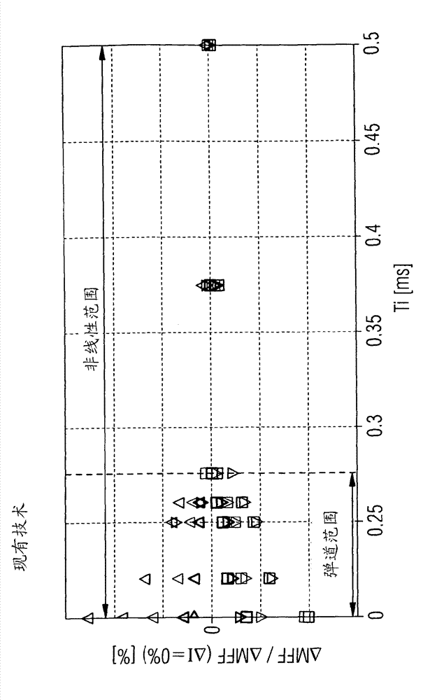
[0067] Figure 3a and Figure 1b The influence of the system tolerance on the injection accuracy as a function of the actuation duration Ti is consistently shown. The effect of a change in the current profile starting from the nominal control is shown in two steps each towards a higher and a lower current level. This change over five different current levels is carried out for the first injector with the smallest tolerance range and the second injector with the largest tolerance range. Altogether, 10 measurement points thus result for...


PUM


Abstract

A method is described for determining a time duration (TiN) for an electric actuation of a valve which has a coil drive, in particular of a direct-injection valve for an internal combustion engine. The method comprises (a) a deactivation of a current flow (400) through a coil of the coil drive, such that the coil is in a currentless state, (b) a detection of a time profile (410) of a voltage induced in the currentless coil, (c) a determination of the closing time of the valve on the basis of the detected time profile (410), and (d) a determination of a time duration (TiN) of the electric actuation of the valve for a future injection process on the basis of the determined closing time. Also described are a corresponding device and a computer program for carrying out the described method.

Description

technical field [0001] The invention relates to the technical field of actuating coil drives for valves, in particular direct injection valves for internal combustion engines of motor vehicles. In particular, the invention relates to a method for determining the duration of an electrical actuation of a valve with a coil drive. The invention also relates to a corresponding device and a computer program for carrying out the method. Background technique [0002] In order to operate modern internal combustion engines and maintain strict emission limit values, the engine control unit determines the air mass contained in the cylinders per working cycle via a so-called cylinder filling model. Depending on the modeled air mass and the desired ratio between the air quantity and the fuel quantity (Lambda (λ)), the corresponding fuel quantity target value (MFF_SP) is injected via the injection valve, also called injector in this document . The fuel quantity to be injected can thus b...

Claims


Application Information

Patent Timeline
Patent Type & Authority Applications(China)
IPC IPC(8): F02D41/20
CPCF02D2041/2055F02D2041/2051F02D41/20F02D41/2467F02D41/247F02D41/402Y02T10/40F02M65/001
Inventor J.比尔E.阿克莱特纳
Owner VTESCO TECH GMBH
Why Eureka
Try Eureka