
vacuum capacitor

一种电容器、真空的技术,应用在电容器、电容器制造、改变电极间距离的电容器等方向,能够解决低效热传递、增加冷却需求、消耗等问题

Active Publication Date: 2016-05-18
COMET INC
View PDF8 Cites 0 Cited by
  • Summary
  • Abstract
  • Description
  • Claims
  • Application Information

AI Technical Summary

Problems solved by technology

An electrode made of tungsten or molybdenum will consume more than three times the electrical energy in the form of heat compared to a similar copper electrode, and this extra heat will be conducted away through the electrode about 2.5 times less efficiently than through a copper electrode
This combination of increased heat generation and less efficient heat transfer means that the cooling requirements for electrodes made of (or coated with) tungsten or molybdenum are greatly increased

Method used


Image

  • vacuum capacitor

Examples


Embodiment Construction

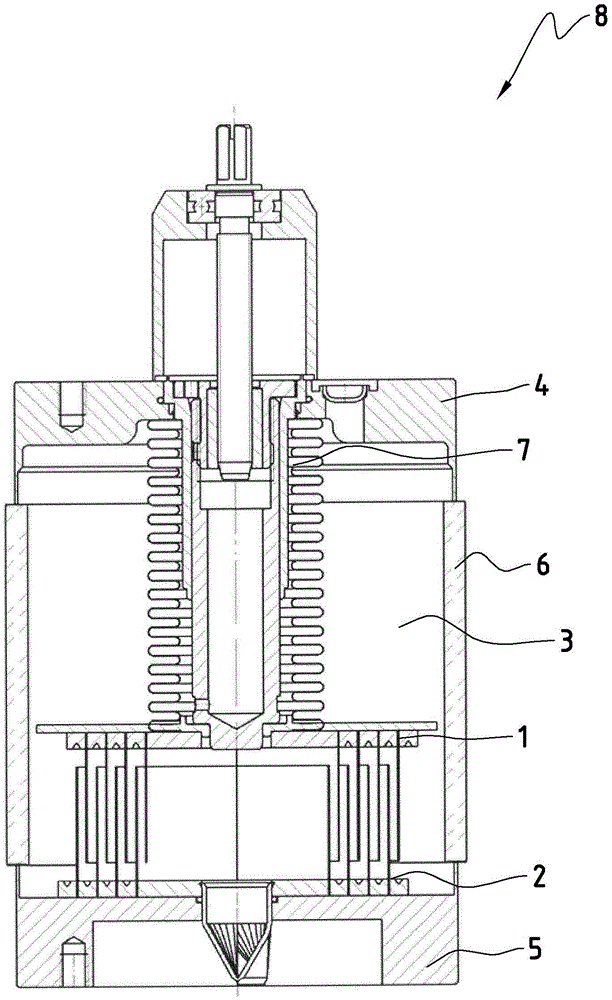
[0026] The present invention will refer to the attached figure 1 described, with figure 1 A typical variable vacuum capacitor arrangement is shown. The figure shows a device in which a set of stationary cylindrical electrodes (2) is spaced apart from a set of movable cylindrical electrodes (1) in a vacuum dielectric (3). The bellows (7) allow relative movement of the movable electrodes while maintaining the integrity of the vacuum dielectric (3) in the housing (4, 5, 6). The housing may comprise a ceramic housing wall (6) vacuum-tight bonded or otherwise secured to an end element, which may be made of an electrically conductive material. Here, it is pointed out that the end elements correspond to the conductive parts (4, 5) according to the invention.

[0027] As described above, selecting an electrode surface material of greater hardness and / or melting point may have the effect of limiting or slowing the development of avalanche breakdown if electrons or ions are ejected f...


PUM

PropertyMeasurementUnit
roughnessaaaaaaaaaa
electrical resistivityaaaaaaaaaa

Abstract

A vacuum capacitor (8) is described, which has at least two electrodes (1, 2) in a vacuum dielectric (3), said electrodes being manufactured or coated with aluminum or an aluminum alloy, and the vacuum capacitor (8 ) comprises an insulating (eg ceramic) part and two or more conducting parts (4, 5).

Description

technical field [0001] The invention relates to the field of vacuum capacitors. Vacuum capacitors are well known in the art and are used in applications requiring high frequency and high power. Common applications include, for example, oscillating circuits used in high-power radio frequency transmission and high-frequency power supplies in the manufacture of semiconductor solar panels and flat panel displays. Background technique [0002] A capacitor consists of two or more conductive surfaces, commonly referred to as electrodes, separated by a dielectric medium. In the case of vacuum capacitors, the dielectric medium is vacuum. Vacuum capacitors usually require high vacuum (10 -6 Torr or better). A vacuum is maintained within an airtight enclosure, which also surrounds the electrodes. A typical case may comprise an insulating ceramic cylinder fitted with a metal ferrule fastened to the ceramic cylinder by a bonding technique which ensures a hermetic seal enabling a hig...

Claims


Application Information

Patent Timeline
Patent Type & Authority Patents(China)
IPC IPC(8): H01G5/01H01G5/14
CPCH01G5/01H01G5/14H01G5/04H01G5/16H01G13/00
Inventor 迈克·阿布雷希特沃尔特·比格勒菲利普·贾吉马克·约阿希姆·米尔德纳
Owner COMET INC
Features
  • Generate Ideas
  • Intellectual Property
  • Life Sciences
  • Materials
  • Tech Scout
  • Unparalleled Data Quality
  • Higher Quality Content
  • 60% Fewer Hallucinations
Learn More