Bionic flytrap driven by shape memory alloy (SMA) wires

A technology of memory alloy wire and Venus flytrap is applied in the field of bionic Venus flytrap robots, which can solve the problems of high driving current, high battery requirements, inconvenient use, etc., and achieves the effects of light weight, good bionic effect and low noise

Inactive Publication Date: 2013-03-13
NORTHEAST FORESTRY UNIVERSITY
View PDF3 Cites 3 Cited by
  • Summary
  • Abstract
  • Description
  • Claims
  • Application Information

AI Technical Summary

Problems solved by technology

[0011] The purpose of the present invention is to provide a bionic Flytrap driven by a shape memory alloy wire to solve the problem that the existing bionic Flytrap robot requires a relatively

Method used


Image

  • Bionic flytrap driven by shape memory alloy (SMA) wires
  • Bionic flytrap driven by shape memory alloy (SMA) wires
  • Bionic flytrap driven by shape memory alloy (SMA) wires

Examples


specific Embodiment approach 1

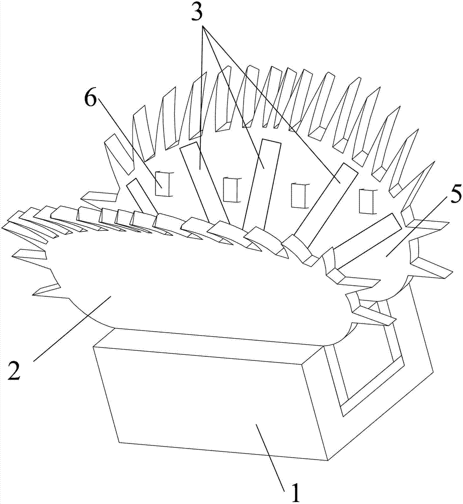
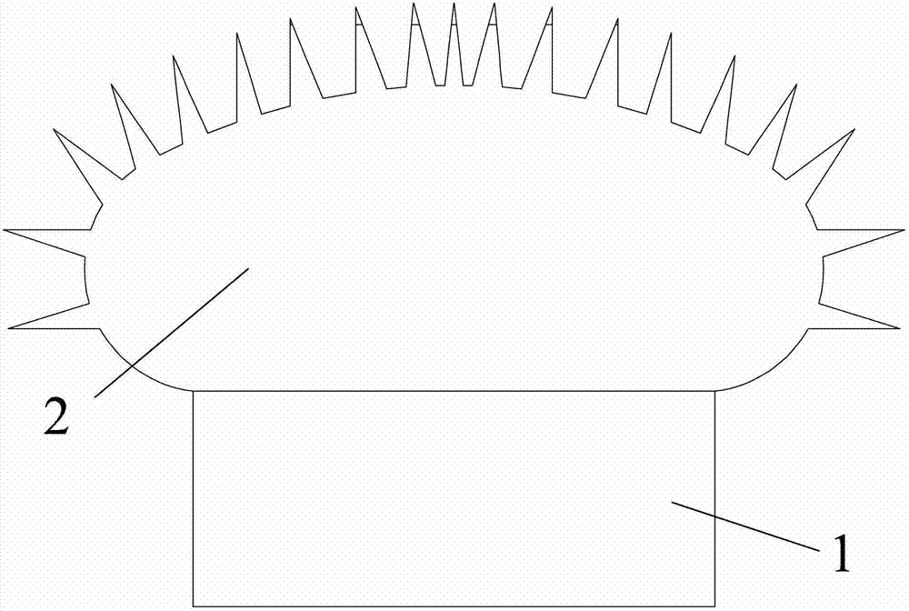
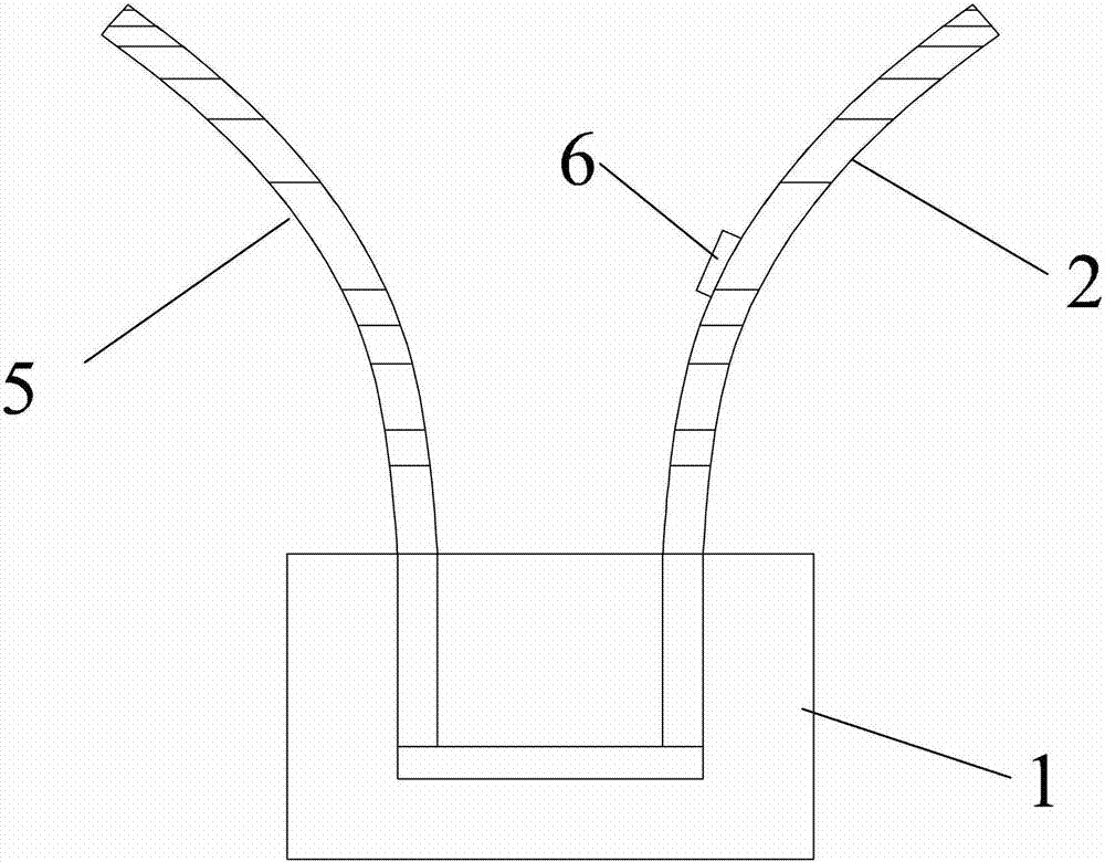
[0023] Specific implementation mode one: as Figure 1-7 As shown, a bionic flytrap driven by a shape memory alloy wire according to this embodiment includes a support 1, a left leaf 2 of the insect trap, a right leaf 5 of the insect trap, a fly sensing device 6 and two sets of shape memory alloy wires Driven reverse bending unit 3, the left blade 2 of the insect trap and the right blade 5 of the insect trap are all made of a material with certain elasticity and the shape of the two is consistent with the blade shape of the Flytraps, the left blade 2 of the insect trap, The right blade 5 of the insect trap is installed on the support 1, a group of reverse bending units 3 driven by shape memory alloy wires are respectively embedded in the left blade 2 of the insect trap, and the right blade 5 of the insect trap, and the fly sensing device 6 is arranged on the left side of the insect trap. Between the blade 2 and the right blade 5 of the insect trap, the reverse bending unit 3 dr...

specific Embodiment approach 2

[0025] Specific implementation mode two: as Figure 1-9As shown, in this embodiment, each reverse bending unit 3 driven by a shape memory alloy wire has a flat curved elongated structure, and each reverse bending unit 3 driven by a shape memory alloy wire includes a shape memory alloy wire 7, a Mongolian The skin 8, the wire 9, the elastic body 10 and the support body 11, the wire 9 and the shape memory alloy wire 7 are connected, the shape memory alloy wire 7 is attached to the elastic body 10, the elastic body 10 is in a curved arc in the initial state, and the shape memory alloy wire 7 The wire 7 is located outside the arc of the elastic body 10, and the skin is wrapped on the shape memory alloy wire 7. The support body 11 is used to fix the elastic body 10 and the shape memory alloy wire 7, and each shape memory alloy wire is fixed by the support body 11. The wire driven reverse bending unit 3 is fixed to the base of the left blade 2 of the insect trap or the right blade 5...

specific Embodiment approach 3

[0026] Specific implementation mode three: as Figure 8-9 As shown, when the shape memory alloy wires 7 in the plurality of reverse bending units 3 in this embodiment are energized and contracted at the same time, the multiple reverse bending units simultaneously produce a bending action, thereby driving the left blade 2 of the insect trap and the right blade of the insect trap 5. Close up and shrink like a Venus flytrap. By controlling the shrinkage and deformation of the shape memory alloy wire 7 through electrical parameters, the bending range of the reverse bending unit can be controlled, so that the left blade 2 of the insect trap and the right blade 5 of the insect trap can form a closed space. Other components and connections are the same as those in the second embodiment.


PUM


Abstract

The invention provides a bionic flytrap driven by shape memory alloy (SMA) wires, and the flytrap belongs to the technical field of robots and aims to solve the problems the driving current which is required by an existing bionic flytrap robot is quite high, the use is not convenient and the like. The left blade (2) of a flytrap clamp and the right blade (5) of the flytrap clamp are arranged on a support (1); a group of reverse bending units (3) driven by the SMA wires are respectively inlaid in the left blade (2) of the flytrap clamp and the right blade (5) of the flytrap clamp; a fly sensing device (6) is arranged between the left blade (2) of the flytrap clamp and the right blade (5) of the flytrap clamp; the two groups of reverse bending units (3) driven by the SMA wires act simultaneously so as to drive the left blade (2) of the flytrap clamp and the right blade (5) of the flytrap clamp to be folded and contract so as to trap a fly into the flytrap clamp. According to the bionic flytrap driven by SMA wires, the fly trapping principle of the flytrap is simulated, an automatic flytrap device which is applicable indoors is provided, and the bionic flytrap has a compact and simple structure, and is convenient to use.

Description

technical field [0001] The invention relates to a bionic flytrap robot driven by a shape memory alloy wire, belonging to the technical field of robots. Background technique [0002] Flies not only affect people's daily work and life, but more importantly, can spread germs, so it is very necessary to catch and eliminate flies. At present, the commonly used methods to eliminate flies mainly include the following: 1. Spraying venom or poisonous mist; 2. Sticking to kill with sticky fly paper; 3. Using various fly cages and fly bottles to trap; 4. Mixing them into various poisonous baits for poisoning ; 5. Kill with a fly swatter. Although the above methods can eliminate flies, most of them have significant disadvantages. The method of spraying or poisoning belongs to chemical insecticide method, which pollutes the environment and is harmful to human health. In addition, long-term use of this method will cause flies to develop antibodies. Killing with a fly swatter can consum...

Claims


Application Information

Patent Timeline
IPC IPC(8): A01M1/10
Inventor 李健朱勋鹏郭艳玲
Owner NORTHEAST FORESTRY UNIVERSITY
Why Eureka
Try Eureka