
High-pressure pulsed turbulent flow pipeline flushing system

A pipeline flushing and high-pressure pulse technology, which is applied in the direction of fluid pressure actuation system components, fluid pressure actuation devices, cleaning hollow objects, etc., can solve the problem of unsatisfactory pipeline flushing in the hydraulic system, shorten the cleaning time, and improve the flushing efficiency. Efficiency, good effect

Active Publication Date: 2013-03-13
WUHAN HUAYE AUTOMATION MACHINERY
View PDF9 Cites 16 Cited by
  • Summary
  • Abstract
  • Description
  • Claims
  • Application Information

AI Technical Summary

Problems solved by technology

[0005] The purpose of the present invention is to overcome the shortcomings and prejudices of the above-mentioned prior art, and provide a high-pressure pulse turbulent flow pipeline flushing system to overcome the problem of unsatisfactory hydraulic system pipeline flushing

Method used


Image

  • High-pressure pulsed turbulent flow pipeline flushing system

Examples


Embodiment 1

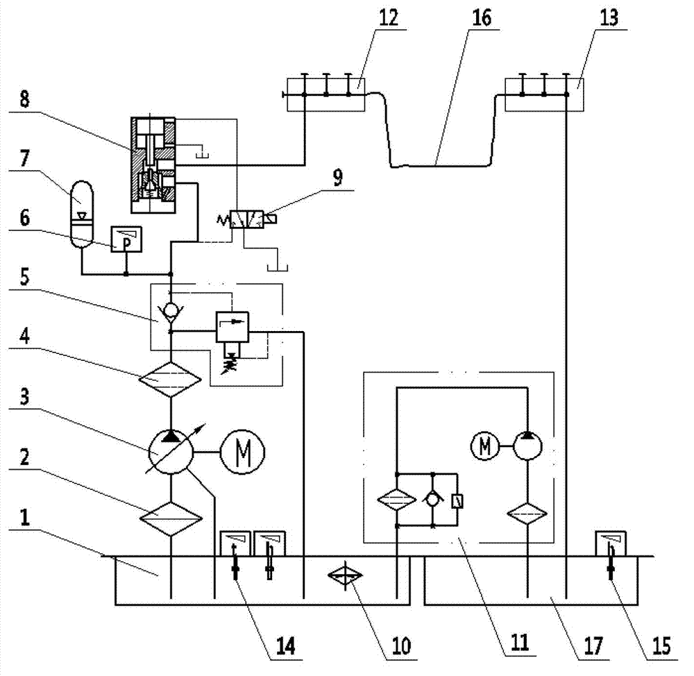
[0024] The figure shows a high-pressure pulse turbulent pipeline flushing system, which is characterized in that the system includes a main oil tank 1 and an auxiliary oil tank 17, the main oil tank 1 is provided with a heater 10, the main oil tank 1 and the auxiliary oil tank 17 The oil pump motor group 3, the pressure sensor 6, the hydraulic control check valve 8 and the flushed pipeline 16 are connected in sequence; the other end of the oil pump motor group 3 is connected to the main oil tank 1, and both ends of the hydraulic control check valve 8 A solenoid valve 9 for controlling the opening and closing of the hydraulic control check valve 8 is provided, a temperature sensor 14 is also provided on the main oil tank 1, and a filter pump set 11 is also connected to the main oil tank 1 and the auxiliary oil tank 17 between them.

[0025] An unloading overflow valve 5 is also provided between the oil pump motor group 3 and the pressure sensor 6, and the other end of the unloading...


PUM


Abstract

The invention discloses a high-pressure pulsed turbulent flow pipeline flushing system. The high-pressure pulsed turbulent flow pipeline flushing system is characterized in that: the system comprises a main oil tank and an auxiliary oil tank, a heater is arranged in the main oil tank, and an oil pump motor assembly, a pressure sensor, a pilot-operated check valve and a flushed pipeline are sequentially connected between the main oil tank and the auxiliary oil tank; the other end of the oil pump motor assembly communicates with the main oil tank, electromagnetic valves for controlling the opening and closing of the pilot-operated check valve are arranged on both ends of the pilot-operated check valve, a temperature sensor is arranged on the main oil tank as well, and a filter pump assembly is connected between the main oil tank and the auxiliary oil tank as well. By adopting an energy accumulator, a constant-power variable pump and an instantly opening valve bank, the system can provide high-pressure, ultrahigh-flow flushing oil in a short time according to the requirements of pipeline varieties, consequently, violently turbulent oil is produced in the pipeline, and oil molecules irregularly and violently move up and down to clean the pipeline in a drilling manner.

Description

Technical field [0001] The invention relates to a high-pressure pulse turbulent flow pipeline flushing system. Background technique [0002] Hydraulic systems generally have hydraulic pipelines, especially large construction machinery, factories and other field equipment hydraulic pump stations, valve blocks, and actuators are all arranged in a distributed installation and connected by pipelines. However, it is very difficult to clean and control the inner wall of the pipeline. It is difficult for the site environment and construction methods to ensure that the inner wall is completely free from pollution. Moreover, this convenient and excessive attention seriously affects the construction efficiency. Therefore, the pipelines of the hydraulic system generally need to be flushed before online operation to eliminate foreign objects in the pipes. [0003] At present, there are generally two types of pipeline flushing: 1. Self-circulation flushing, which is to short-circuit the end of...

Claims


Application Information

Patent Timeline
Patent Type & Authority Applications(China)
IPC IPC(8): B08B9/032F15B21/00F15B21/04
Inventor 兰年山
Owner WUHAN HUAYE AUTOMATION MACHINERY
Learn More