Drawing mechanism for camshaft sleeve

A camshaft and pull rod technology, applied in metal processing, metal processing equipment, manufacturing tools, etc., can solve the problems of ejector rod 1 breaking, large impact force, and pressure instability of ejector rod 1

Inactive Publication Date: 2013-03-13
WEICHAI POWER CO LTD
View PDF7 Cites 3 Cited by
  • Summary
  • Abstract
  • Description
  • Claims
  • Application Information

AI Technical Summary

Problems solved by technology

When the above-mentioned tooling is used to drive in at room temperature, the impact force is too large and the working process is rough, which may easily cause the camshaft sleeve 9 to be curled and cannot be used. However, after cooling with liquid nitrogen and driving in, the camshaft sleeve 9 becomes hard and brittle. Very prone to cracking, the assembly of t

Method used


Image

  • Drawing mechanism for camshaft sleeve
  • Drawing mechanism for camshaft sleeve
  • Drawing mechanism for camshaft sleeve

Examples


Embodiment Construction

[0039] In order to enable those skilled in the art to better understand the technical solutions of the present invention, the present invention will be further described in detail below in conjunction with the accompanying drawings and specific embodiments.

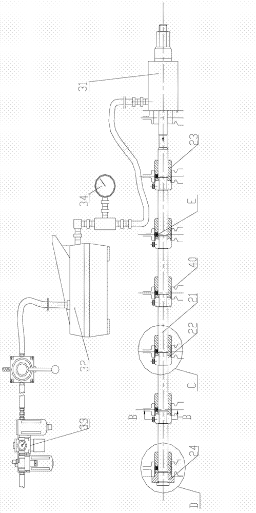
[0040] Please refer to Figure 3-4 , image 3 It is a structural schematic diagram of a specific embodiment of the cam bushing pull-in mechanism provided by the present invention; Figure 4 for image 3 The partially enlarged schematic diagram of part C in the middle.

[0041] The pull-in mechanism of the cam bushes 41 in this embodiment can pull several cam bushes 41 into the installation holes of the cam bushes 41 at the same time. image 3 Taking seven cam bushings 41 as an example, that is, the body 40 is provided with seven mounting holes arranged in the axial direction, and seven cam bushings 41 need to be installed. In the figure, there is a matching gap between the rightmost mounting hole and the cam bushing 4...


PUM


Abstract

The invention discloses a drawing mechanism for camshaft sleeves, which comprises a pre-guide sleeve capable of driving the camshaft sleeves to pass through camshaft installation holes, a draw bar, a check block and a drive part, wherein the draw bar can penetrate through the pre-guide sleeve and can sequentially penetrate through various installation holes arranged in the axial direction; the check block is sleeved on the draw bar in a clamping way; the drive part is used for drawing the draw bar to move axially along the installation holes so as to draw the camshaft sleeves into the installation holes, and when drawn, the camshaft sleeves are located between the check block and the pre-guide sleeve. According to the drawing mechanism, the stress born by the camshaft sleeves in the drawing process is relatively soft, and the camshaft sleeves can be smoothly drawn at the normal temperature without the crack phenomenon. In addition, a bar body has the characteristics that the bar body is unstable when pressed but stable when drawn, so that the draw bar in the drawing mechanism is not easily broken or damaged to have a long service life. Furthermore, the drawing mechanism can draw multiple camshaft sleeves into the corresponding installation holes at one time, so that the installation efficiency is greatly improved.

Description

technical field [0001] The invention relates to the technical field of engineering machinery, in particular to a pull-in mechanism of a camshaft sleeve. Background technique [0002] For engines, especially high-power diesel engines, the installation of camshaft sleeves is an essential process. In order to achieve tight fit, the installation holes of the camshaft sleeves set on the diesel engine body and the interference of the camshaft sleeves are relatively large. , the minimum interference is basically around 0.08mm, and the maximum interference can reach 0.15mm. [0003] At present, the traditional installation method of the camshaft sleeve is to drive in with a special tool, please refer to Figure 1-2 understand, figure 1 It is a structural schematic diagram of a typical camshaft sleeve driving tool; figure 2 for figure 1 A-A to the sectional view. [0004] The driving tool mainly includes a push rod 1, a stepping gasket 2, a front guide sleeve 4, a rear guide s...

Claims


Application Information

Patent Timeline
IPC IPC(8): B23P19/027
Inventor 白林坡刘国千尹丰云
Owner WEICHAI POWER CO LTD
Why Eureka
Try Eureka