
Drill rod detaching device for hydraulic rig

A technology of dismantling device and hydraulic drilling rig, applied in drill pipe, drill pipe, drilling equipment, etc., can solve problems such as deformation of drill pipe, excessive handle, and injury caused by misfit, so as to avoid personal injury accidents, reduce labor intensity, Easy-to-use effects

Inactive Publication Date: 2014-12-10
CHONGQING SONGZAO COAL & ELECTRICITY CO LTD
View PDF5 Cites 0 Cited by
  • Summary
  • Abstract
  • Description
  • Claims
  • Application Information

AI Technical Summary

Problems solved by technology

During the disassembly process of the drill pipe, due to the tight threaded connection of the drill pipe, the operator often uses a wrench to tap the drill pipe when loosening the connection of the drill pipe. The drill pipe is deformed due to the knocking of the drill pipe, resulting in the drill pipe and gas water slag The seal of the integrated device of the separator and the extraction is not good, which in turn causes the air to enter the gas drainage pipeline due to poor sealing when the drill hole penetrates the coal seam for extraction, resulting in a decrease in the concentration of the gas drainage
And present drilling rig drill rod dismounting method also has following problems: the one, when dismantling drill rod, unscrew drill rod by manpower operation dead wrench, and drill rod is in drilling process, often connects tighter, when manpower can't unscrew the drill rod When the drill rod is used, it can only be disassembled by reverse rotation of the machine, but the handle of the dead wrench is too long and the radius of rotation is too large. When the operation or coordination is wrong, it is easy to throw the wrench off the drill pipe and hurt people.
Second, the operator of the downhole drilling rig disassembles the drill pipe. In order to disassemble the speed, the disassembly depends entirely on the usual cooperation experience, which is easy to subjectively cause coordination errors and hurt people.

Method used


Image

  • Drill rod detaching device for hydraulic rig
  • Drill rod detaching device for hydraulic rig
  • Drill rod detaching device for hydraulic rig

Examples


Embodiment Construction

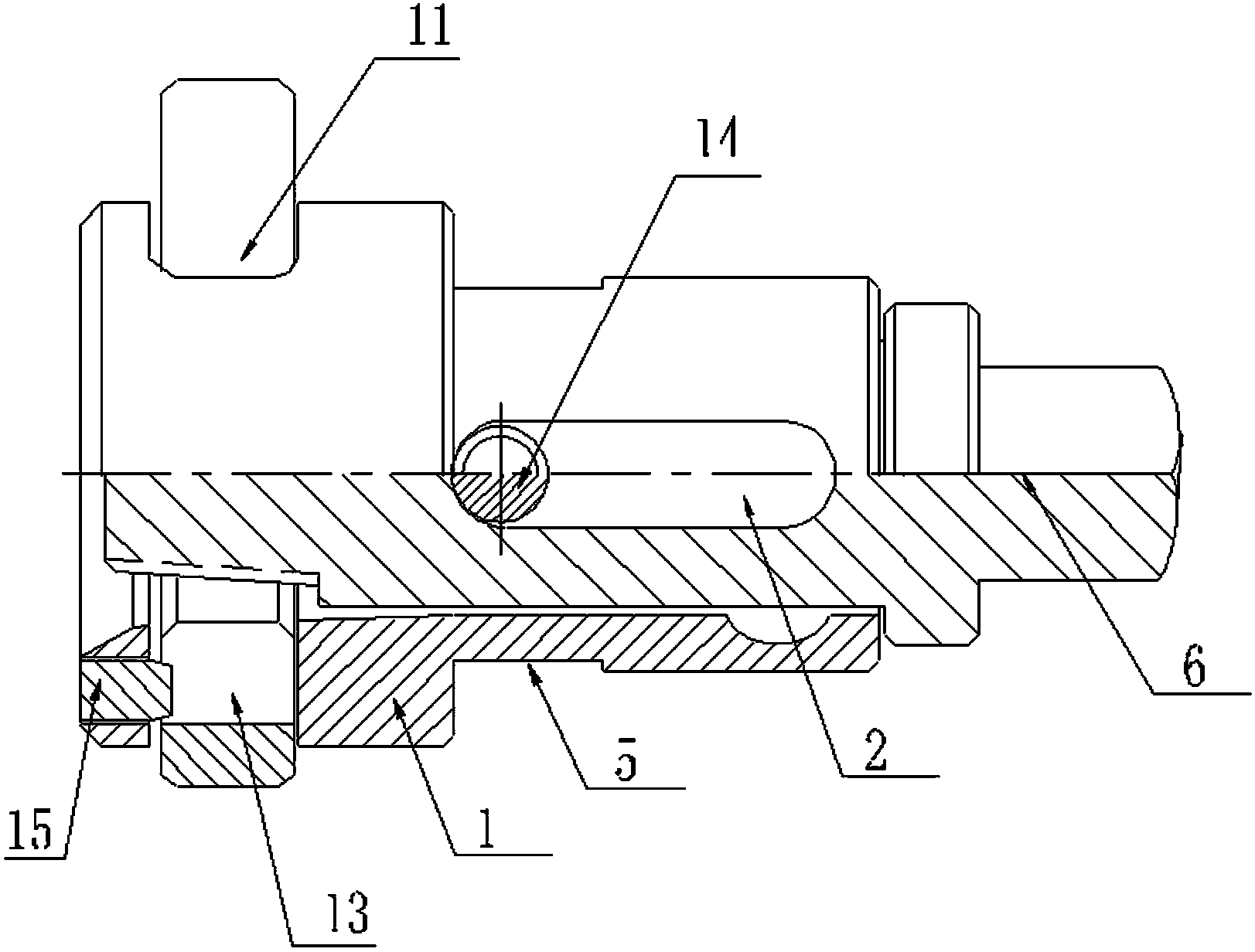
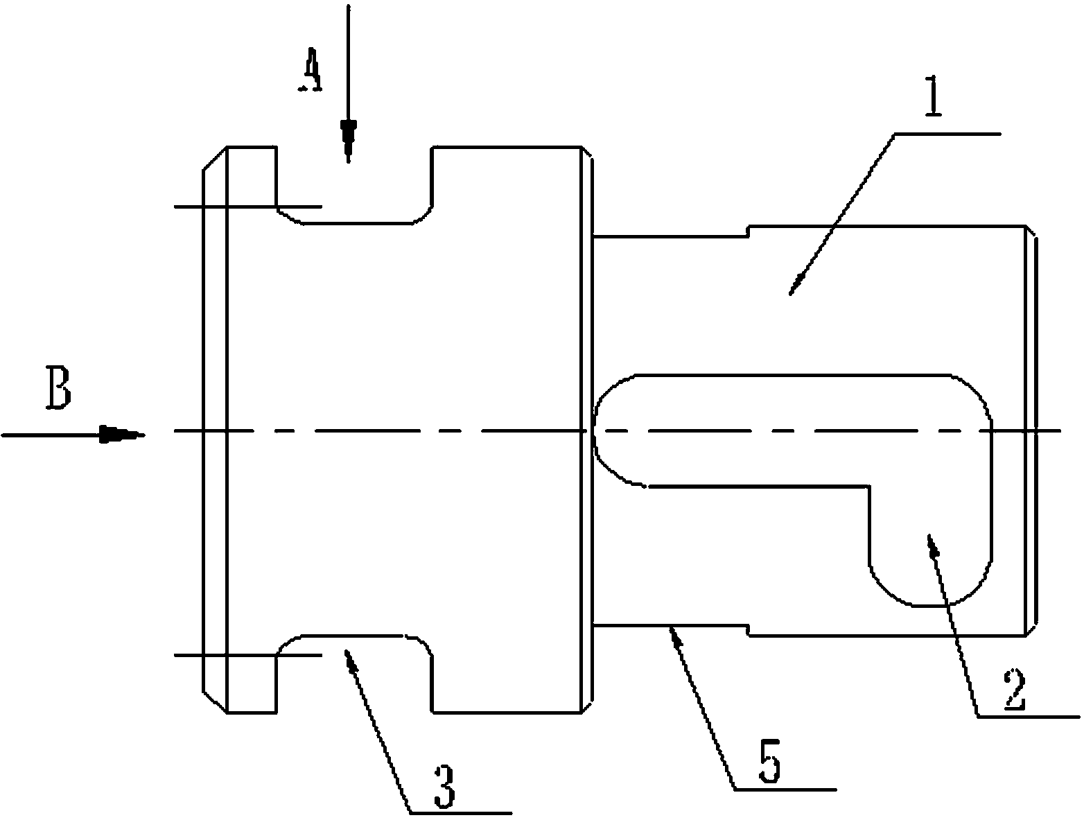
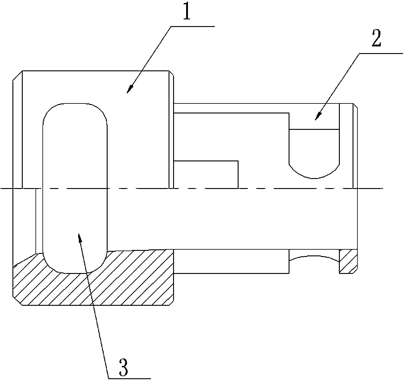
[0024] Reference Figure 1 to Figure 9 The drill rod disassembly device of the hydraulic drilling machine includes a sleeve 1, a cylindrical guide rod 6 and a clamp 11 for clamping the drill rod. One end of the sleeve 1 is provided with a clamp socket 3 radially penetrating the sleeve, and on the sleeve wall An L-shaped positioning guide groove 2 is provided. Preferably, the sleeve 1 is provided with two L-shaped positioning guide grooves 2, and the two L-shaped positioning guide grooves 2 are located on the same diameter of the sleeve 1. The sleeve 1 is symmetrically provided with a cutting plane 5 on the circumferential surface, which is convenient for holding the sleeve 1 for axial movement or circumferential rotation. The sleeve 1 is provided with two symmetrical axial end faces at the end where the clip socket 3 is provided. The positioning holes 4 for limiting the position of the clip 11 are respectively arranged beside the sleeve barrel holes. The clip 11 is provided wi...


PUM


Abstract

The invention relates to a drill rod detaching device for a hydraulic rig. The drill rod detaching device comprises a sleeve, a cylindrical guide rod and a clamp, wherein the clamp is used for clamping a drill rod; one end of the sleeve is provided with a clamp faucet which passes through the sleeve radially; the wall of the sleeve is provided with an L-shaped positioning guide groove; the clamp is provided with a special-shaped through hole for locking the drill rod; the profile of the special-shaped through hole consists of a superior arc section and a rectangular section; the clamp is inserted into the clamp faucet of the sleeve; one end of the cylindrical guide rod is set as a prism section, and the other end of the cylindrical guide rod is set as a threaded section; the cylindrical guide rod is provided with a pin hole in the radial direction; the cylindrical guide rod is in interference fit in the sleeve; a positioning pin inserted into the radial pin hole of the cylindrical guide rod is in sliding fit with the L-shaped positioning guide groove; the cylindrical guide rod is locked in the sleeve; and a positioning pin moving degree of freedom is left for the L-shaped positioning guide groove. The invention provides the drill rod detaching device for the hydraulic rig, which is used for detaching the drill rod from threaded connection. The drill rod detaching device has the advantages of improvement on the drill rod detaching safety and reduction in the labor intensity.

Description

Technical field [0001] The invention relates to a drainage drilling rig technology for a mine drainage system, in particular to a hydraulic drilling rig drill rod disassembly device. Background technique [0002] The drainage drilling rig is used in the mine drainage system to drill between the ore layers and control the gas by drainage. [0003] The length of the drill pipe of a mine extraction rig is generally about 800 mm, and a drilling depth is between 50 and 150 meters. When drilling, each drill rod is connected by the rotation of the drilling machine. After a drilling is completed, the drill rods need to be disassembled one by one. In the process of drill pipe disassembly, due to the tight threaded connection of the drill pipe, the operator often uses a wrench to strike the drill pipe when loosening the drill pipe connection. The drill pipe is deformed by striking the drill pipe, resulting in the drill pipe and gas water slag The sealing of the integrated device of the sep...

Claims


Application Information

Patent Timeline
Patent Type & Authority Patents(China)
IPC IPC(8): E21B19/18
Inventor 覃乐黄小于张鹏伟隆念
Owner CHONGQING SONGZAO COAL & ELECTRICITY CO LTD
Learn More