Rotation braking device of tower crane

A tower crane, slewing brake technology, applied in the direction of cranes, drum brakes, brake types, etc., can solve the problems of large brake device size, reduced braking effect, difficult length and elasticity, etc., to achieve axial The effect of small size, large braking force and simple structure

Inactive Publication Date: 2013-03-13
江苏华商企业管理咨询服务有限公司
View PDF0 Cites 10 Cited by
  • Summary
  • Abstract
  • Description
  • Claims
  • Application Information

AI Technical Summary

Problems solved by technology

[0002] At present, the moving device of the tower crane generally consists of a coupling, a lower bracket, an electromagnet, a connecting shaft, a spacer, a bearing, an upper bracket, a pressure plate, a friction plate, a spring, a tie rod, an armature, and a rotary reducer. Among them, the bracket is installed around the output shaft of the rotary reducer, and the brake composed of the above parts is installed above the bracket. The electromagnet operates the braking device through three pull rods. The main disadvantages of it are: The axial size of the bearing is too large; the bearing is greatly affected by the high temperature in the work, the lubricating oil in the bearing is easy to thin, lose, and the life of the bearing is reduced, which leads to the failure of the whole equipment to work normally. At the same time, because the three compression springs are not It is easy to maintain the same length and elasticity, causing the friction plate to tilt, reducing the braking effect, and easily causing safety accidents; in addition, due to the complexity of the mechanism, the failure rate is high

Method used


Image

  • Rotation braking device of tower crane
  • Rotation braking device of tower crane
  • Rotation braking device of tower crane

Examples


Embodiment Construction

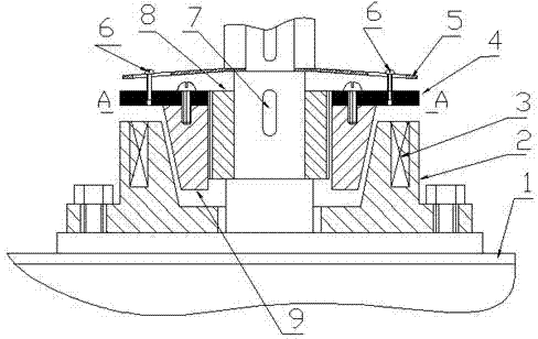
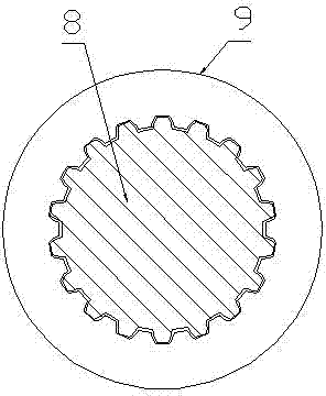
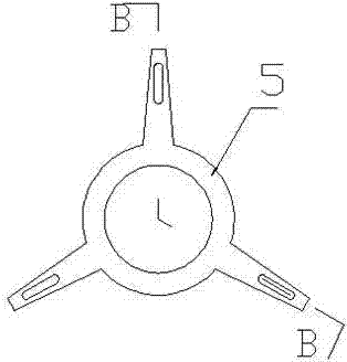
[0011] Tower crane slewing braking device, including slewing reducer 1, brake seat 2, electromagnetic coil 3, armature 4, spring leaf 5, hanging wire 6, key 7, positioning guide spline 8, brake drum 9, brake seat 2 Installed and fixed on the box around the output shaft of the slewing reducer 1, the brake seat 2 is made of a material with better magnetic permeability, and an inner cone is formed in the middle of the brake seat 2, and the tip of the cone is downward, and on the brake seat 2 An electromagnetic coil 3 is inlaid inside, and a positioning guide spline 8 is installed on the output shaft of the slewing reducer 1 through a key 7, and a brake drum 9 is installed on the outer circle of the positioning guide spline 8 in a spline-fitting manner. The outer circle of the moving drum 9 has the same taper as the middle of the brake seat 2, and the brake drum 9 has the degree of freedom to slide relative to the positioning guide spline 8 in the axial direction, but has no degree...


PUM


Abstract

The invention relates to a rotation braking device of a tower crane. A brake seat is fixedly installed on a case body around an output shaft of a rotation speed reducer, an inner taper is extendeds out of the middle part of the brake seat, and an electromagnetic coil is inlaid in the brake seat; a positioning guide spline is installed on the output shaft of the rotation speed reducer through a key, a brake drum is installed on the outer circle of the positioning guide spline in a spline fit mode, and the outer circle of the brake drum has the same taper as the middle part of the brake seat; an armature is fixedly arranged on the plane of the upper end of the brake drum by using a screw, and a spring piece is arranged on the output shaft of the rotation speed reducer, which is positioned on the upper part of the armature; and the armature is hung in a long hole of the spring piece through a hang spring. The rotation braking device has the advantages of simple structure, small axial size, larger braking force and long service life.

Description

technical field [0001] The invention relates to a tower crane, in particular to a slewing braking device for a tower crane, and belongs to the technical field of tower cranes. Background technique [0002] At present, the moving device of the tower crane generally consists of a coupling, a lower bracket, an electromagnet, a connecting shaft, a spacer, a bearing, an upper bracket, a pressure plate, a friction plate, a spring, a tie rod, an armature, and a rotary reducer. Among them, the bracket is installed around the output shaft of the rotary reducer, and the brake composed of the above parts is installed above the bracket. The electromagnet operates the braking device through three pull rods. The main disadvantages of it are: The axial size of the bearing is too large; the bearing is greatly affected by the high temperature in the work, the lubricating oil in the bearing is easy to thin, lose, and the life of the bearing is reduced, which leads to the failure of the whole ...

Claims


Application Information

Patent Timeline
IPC IPC(8): F16D49/00F16D65/18B66C23/62B66C23/94F16D121/20
Inventor 李福新
Owner 江苏华商企业管理咨询服务有限公司
Why Eureka
Try Eureka