Radar foresight super-resolution imaging method

A super-resolution imaging and forward-looking technology, which is applied in the reflection/re-radiation of radio waves, the use of re-radiation, measurement devices, etc., can solve the problems of difficult practical application, limited azimuth resolution, etc. Distinguish imaging performance, overcome scene constraints, avoid effects of synchronization

Active Publication Date: 2013-03-13
UNIV OF ELECTRONICS SCI & TECH OF CHINA
View PDF4 Cites 42 Cited by
  • Summary
  • Abstract
  • Description
  • Claims
  • Application Information

AI Technical Summary

Problems solved by technology

[0004] For forward-looking imaging of moving platform radar, especially how to improve the azimuth resolution, the document "Airborne Radar Single-Pulse Forward-Look Imaging Algorithm, Chinese Journal of Image and Graphics, 2010, 15 (3): P462-469" adopts Monopulse technology is used for forward-looking imaging. This technology is based on the principle of single-pulse angle measurement and is suitable for strong point targets. For complex landforms, due to the existence of multiple scattering centers, serious angular scintillation will occur; the literature "A new Sector Imaging Radar for Enhanced Vision–SIREV” (SPIE Conference on Enhanced and Synthetic Vision, 1999, pp.39-47, Florida), uses an...

Method used


Image

  • Radar foresight super-resolution imaging method
  • Radar foresight super-resolution imaging method
  • Radar foresight super-resolution imaging method

Examples


Embodiment Construction

[0019] The method of the present invention will be further elaborated below in conjunction with the accompanying drawings and specific embodiments.

[0020] Before describing the method of the present invention, the process of echo acquisition will be explained first:

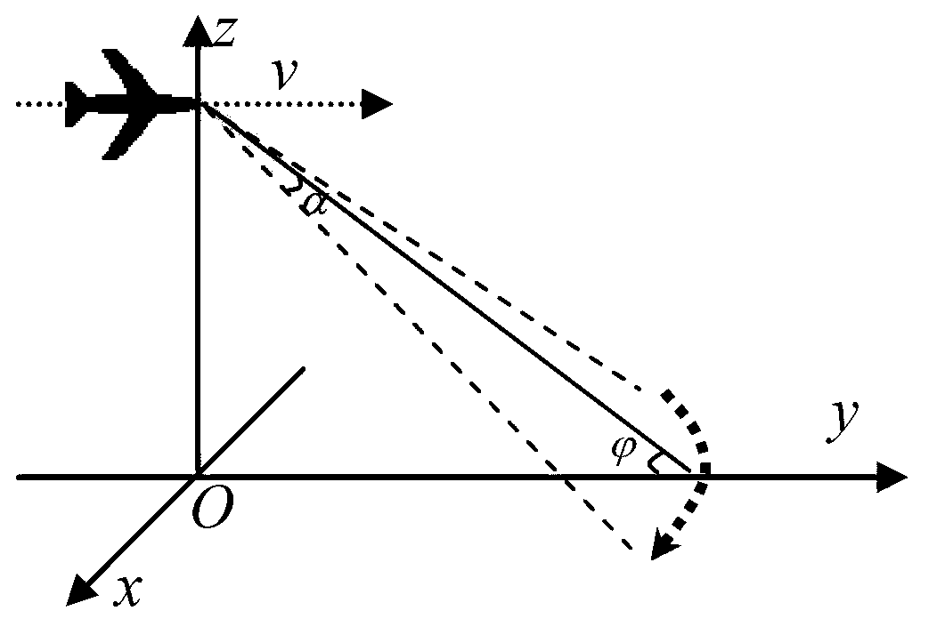
[0021] While the platform is moving at a high speed, the antenna scans from the left of the heading to the right of the heading (or from the right to the left), and transmits the chirp signal and receives and stores the echo data according to a certain pulse repetition frequency.

[0022] figure 1 A schematic diagram of the forward-looking scanning operation of the airborne radar in this embodiment, in which the azimuth beam width of the radar antenna is θ w =3°, the antenna scans the area of ​​±10° in front of the carrier, the scanning speed is ω=30° / s, the speed of the carrier is v=100m / s, the wavelength of the transmitter signal is λ=0.03m, and the bandwidth is B=10MHz, FM slope is K r =6×10 12 The l...


PUM


Abstract

The invention discloses a radar foresight super-resolution imaging method which specifically includes: distance toward pulse compression, distance walking corrosion, distance toward inverse fast fourier transform (IFFT), determination of iterations and azimuth deconvolution. The radar foresight super-resolution imaging method performs azimuth modeling on echo scanned by a radar antenna in foresight mode to enable the echo to be in convolution, and estimates front ground feature distribution information in a deconvolution method; and additionally, based on noise statistical property, optimum iterations can be determined according to iteration deconvolution, so that radar can obtain better foresight super-resolution imaging performance. Compared with the background technology, the radar foresight super-resolution imaging method overcomes the restrains on scene of a single-pulse imaging technology and limitation on platform dimension of an array imaging method, further solves the problems of complex synchronization, motion compensation and the like of double-foundation synthetic aperture radar (SAR) and can effectively obtain ground feature distribution information of the area dead ahead the platform.

Description

technical field [0001] The invention belongs to the technical field of radar imaging, in particular to a forward-looking super-resolution imaging method suitable for a moving platform radar. Background technique [0002] Radar forward-looking imaging refers to obtaining the distribution information of ground objects in the area directly in front of the platform. The development of the forward-looking imaging capability of the radar onboard the moving platform is beneficial to improve the pilot's judgment and identification of the distant terrain and the platform's autonomous navigation ability, improve the platform's reconnaissance, surveillance, positioning and identification capabilities, and can realize the accurate positioning of the airdrop site. The fields of autonomous landing, autonomous navigation and forward-looking reconnaissance are of great significance. [0003] At present, in the process of imaging the ground with the radar on the moving platform, the high ra...

Claims


Application Information

Patent Timeline
IPC IPC(8): G01S13/89G01S7/41
Inventor 李文超蒋文黄钰林杨建宇刘喆武俊杰李中余
Owner UNIV OF ELECTRONICS SCI & TECH OF CHINA
Why Eureka
Try Eureka