Integrated energy extracting device for power electronic equipment

An energy harvesting device and power electronics technology, applied in the directions of transformer/inductor coil/winding/connection, reactive power compensation, reactive power adjustment/elimination/compensation, etc. Performance requirements, cable threading difficulties and other problems, to achieve the effect of shortening the production cycle, easy implementation, and good heat dissipation conditions

Active Publication Date: 2013-03-13
STATE GRID CORP OF CHINA +1
View PDF3 Cites 3 Cited by
  • Summary
  • Abstract
  • Description
  • Claims
  • Application Information

AI Technical Summary

Problems solved by technology

The above two energy harvesting devices have the following disadvantages: 1. Due to the large number of uses, the installation mechanism needs to be designed separately in structure, and the fixing method is relatively cumbersome
2. The cables must pass through the centers of all energy-taking devices in turn. The size of the center hole of the device must be strictly controlled, and t

Method used


Image

  • Integrated energy extracting device for power electronic equipment
  • Integrated energy extracting device for power electronic equipment
  • Integrated energy extracting device for power electronic equipment

Examples


Embodiment Construction

[0027] The specific implementation manners of the present invention will be further described in detail below in conjunction with the accompanying drawings.

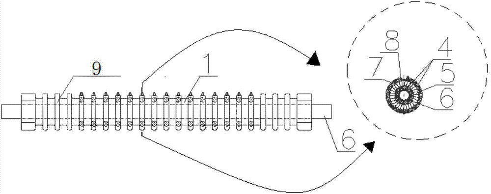
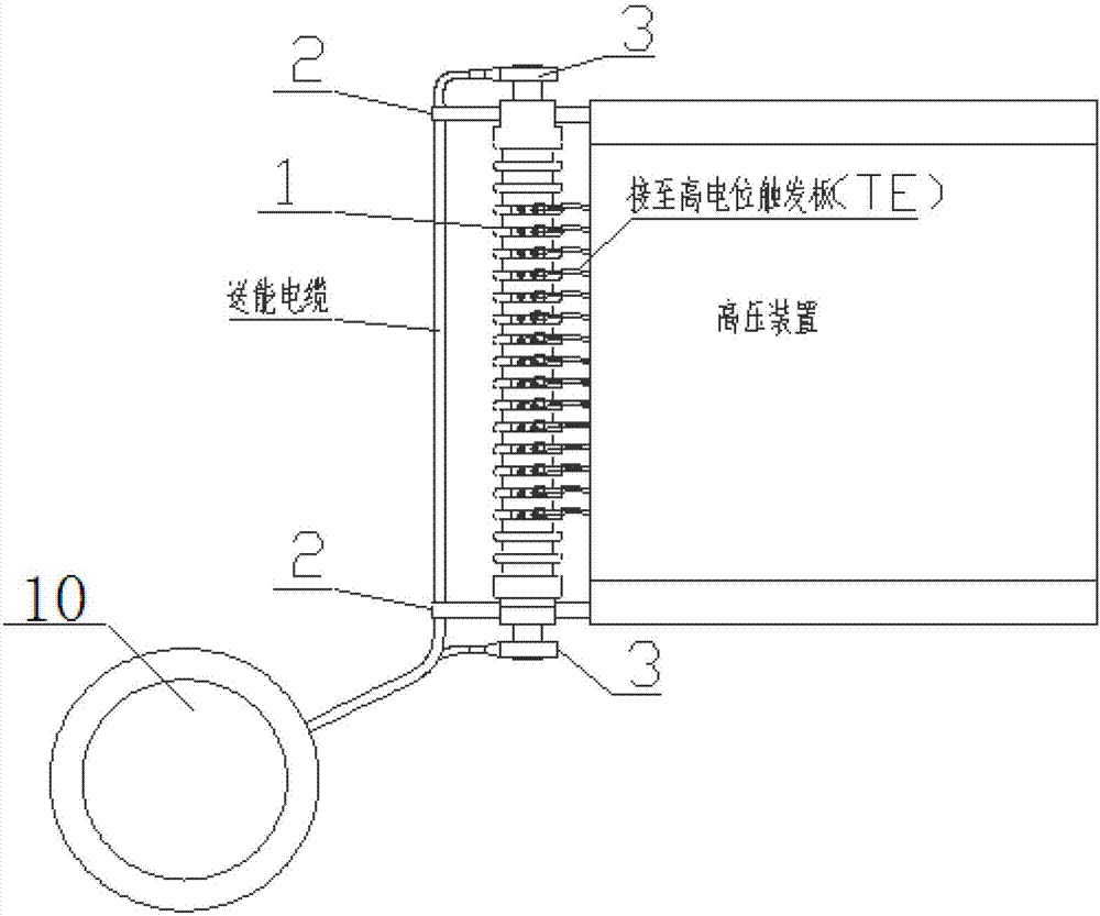
[0028] An integrated energy harvesting device for power electronic equipment provided in this embodiment, its structure diagram is as follows figure 1 As shown, it includes a current converter 1, a cable fixing device 2, a primary side terminal 3 and a transformer 10; this embodiment takes two cable fixing devices as an example for illustration. In the axial direction of the current transformer 1, there are two symmetrical cable fixing devices 2 that pass through the center of the current transformer 1; at the same time, two primary side terminals 3 are respectively arranged at both ends of the current transformer 1, each One end of each primary-side terminal 3 is connected to the lead-out cable of the power transformer, and the other end is connected to the hard conductor 6 of the primary winding of the current transfor...


PUM


Abstract

The invention discloses an integrated energy extracting device for power electronic equipment. The device comprises a current transformer (1), a cable fixing unit (2), primary side terminals (3) and a transformer (10), wherein at least one cable fixing unit (2) is fixed on the current transformer (1) through screws, and two primary side terminals (3) are arranged at two ends of the current transformer (1) respectively and connected with the transformer (10) through cables. The device mainly supplies working energy for a trigger board (TE board) working with a high potential, and is provided with superior electrical and mechanical properties, simple in structure and easy to implement.

Description

technical field [0001] The invention relates to the field of power systems, in particular to an integrated energy harvesting device for power electronic equipment. Background technique [0002] The TSC thyristor valve of the static var compensation device (SVC) needs to be triggered at the zero-crossing point of the thyristor voltage for the first time, and after being turned on, the reverse thyristor should be triggered to keep the capacitor connected to the system after the current zero-crossing point is naturally turned off. Therefore, the high-potential trigger board (TE board) mostly uses external energy supply, that is, adopts the current energy delivery method, and takes the current of a separate low-voltage system as the source of energy for the thyristor to start. The energy transmission system mainly includes energy transmission transformers and cables, and the energy harvesting part is mainly energy harvesting devices. In the existing scheme, the energy harvestin...

Claims


Application Information

Patent Timeline
IPC IPC(8): H02J3/18H01F27/30H01F27/32
CPCY02E40/30
Inventor 张雷常忠王承民王爱袁洪亮郎平张伟华任西周
Owner STATE GRID CORP OF CHINA
Why Eureka
Try Eureka