Pulse signal transmission method

A technology of pulse signal and signal conditioning circuit, applied in pulse generation, pulse shaping, pulse technology and other directions, can solve problems such as large volume, achieve the effect of small volume, low cost and simple realization

Inactive Publication Date: 2013-03-13
CHINA SHIPBUILDING IND HAIBOWEI JIANGSU TECH DEV
View PDF4 Cites 3 Cited by
  • Summary
  • Abstract
  • Description
  • Claims
  • Application Information

AI Technical Summary

Problems solved by technology

[0003] However, in the case of high-voltage isolated transmission, the volume occupied by the photoelectric transmission unit is relatively large, and the sealing problem of the optical fiber connector needs to be solved when the photoelectric sending and receiving device is used for potting in high-voltage insulation.

Method used


Image

  • Pulse signal transmission method
  • Pulse signal transmission method

Examples


Embodiment Construction

[0026] The invention provides a pulse signal transmission method, which can meet the requirements of pulse signal conditioning under high-voltage isolated transmission occasions, and has simple implementation and low manufacturing cost.

[0027] The present invention will be further described in detail below in conjunction with the accompanying drawings and specific embodiments.

[0028] The specific implementation steps of a pulse signal transmission method are as follows:

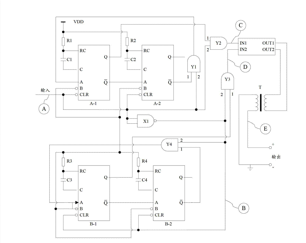
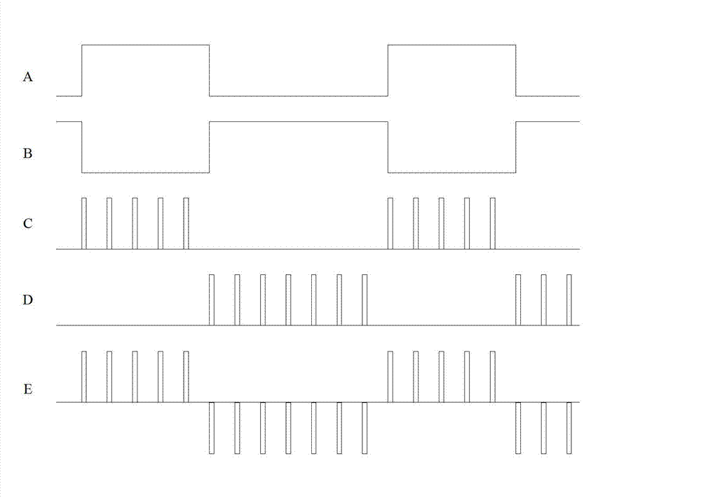
[0029] First, the pulse signal is input into the signal conditioning circuit based on the synchronous bistable multivibrator;

[0030] Secondly, the signal conditioning circuit converts the pulse signal into a narrow pulse signal and outputs it through an isolation transformer;

[0031] Finally, the receiving end converts the received narrow pulse signal into the original pulse signal.

[0032] as attached figure 1 As shown, the signal conditioning circuit based on the synchronous flip-flop includes fo...


PUM


Abstract

The invention discloses a pulse signal transmission method, and belongs to the field of signal processing. A signal conditioning circuit based on a synchronous bi-stable multivibrator conditions input signals, and a receiving terminal converts the conditioned signals into original signals. The signal conditioning circuit comprises an isolation transformer, an integrated pulse drive circuit and two repeatable triggered mono-stable integrated circuits, wherein the two repeatable triggered mono-stable integrated circuits form the bi-stable multivibrator, the integrated pulse drive circuit is used for achieving two-channel signal drive, and the isolation transformer is used for converting unipolar-pulse or direct-current signals into bipolar-pulse modulating signals. The pulse signal transmission method can meet pulse signal modulation requirements under high-voltage isolated transmission occasions, and is simple to implement and low in implementation cost.

Description

technical field [0001] The invention relates to a pulse signal transmission method and belongs to the technical field of signal processing. Background technique [0002] In some pulse or DC working equipment, there will be a situation where the pulse continues to change in a large range, and the pulse width varies from nanoseconds to tens of milliseconds. At this time, the traditional transformer used for pulse isolation transmission is no longer applicable. Usually The solution adopted is to use the photoelectric conversion method to convert the pulse signal into an optical signal, and then use the optical fiber to realize the isolated transmission of the pulse signal. [0003] However, in the case of high-voltage isolated transmission, the volume occupied by the photoelectric transmission unit is relatively large, and the sealing problem of the optical fiber connector needs to be solved when the photoelectric sending and receiving device is used for potting in high-voltage...

Claims


Application Information

Patent Timeline
Patent Type & Authority Applications(China)
IPC IPC(8): H03K3/033H03K5/04
Inventor 蒋洪卫沙亮张彦
Owner CHINA SHIPBUILDING IND HAIBOWEI JIANGSU TECH DEV
Why Eureka
Try Eureka