Self-controlling type outer irradiation photochemical reaction device

A chemical reaction and equipment technology, applied in the field of photochemical reaction devices, can solve problems such as the inability to fully realize automatic control integration, and achieve the effects of being beneficial to accuracy, convenience, and strong sampling adaptability

Inactive Publication Date: 2013-03-20
GUANGXI UNIV
View PDF9 Cites 13 Cited by
  • Summary
  • Abstract
  • Description
  • Claims
  • Application Information

AI Technical Summary

Problems solved by technology

Although the reactor can adjust the ultraviolet irradiation, the sample is evenly irradiated during the rotation process

Method used


Image

  • Self-controlling type outer irradiation photochemical reaction device
  • Self-controlling type outer irradiation photochemical reaction device

Examples


Example Embodiment

[0027] Example 1:

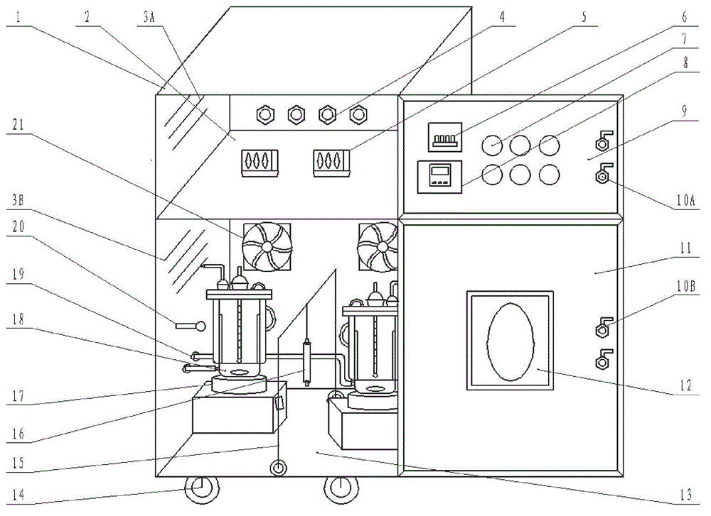
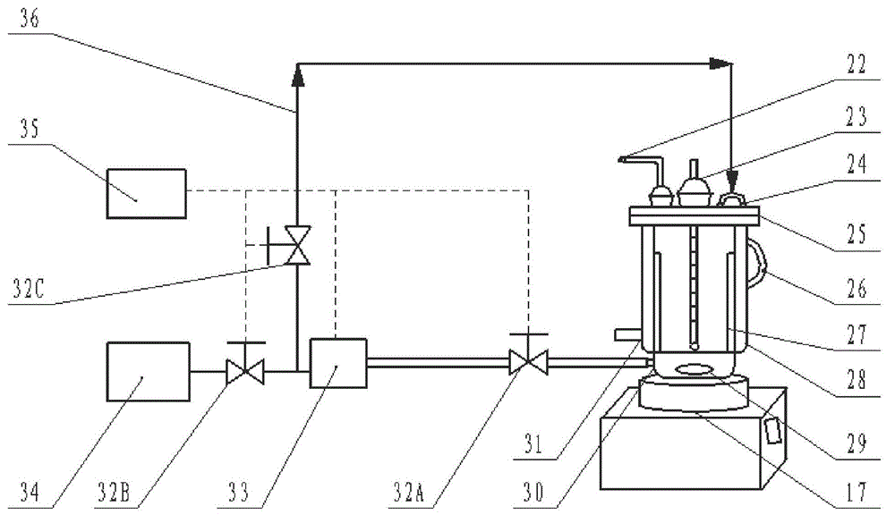
[0028]As shown in the figure, the self-controlled external photochemical reaction equipment is provided with a box body 1, which is divided into an upper box body 2 and a lower box body 13, and four pulleys 14 are arranged at the bottom of the box body 1 to facilitate the movement of the equipment. Upper box body 1 is provided with upper door panel 9, and upper door panel 9 is provided with locking switch 10A, is provided with cable hole 4 behind upper box body 1, for cables to pass through, and upper box body 2 side panels are provided with heat dissipation windows 3A. The control system of the self-controlled external photochemical reaction equipment is installed in the upper box body 2 . Power protection switch 6, relay 7, computer time control switch 35 and microcomputer controller 8 are installed on the upper door panel 9, and ballast 5 is installed on the horizontal plate of upper casing 2. The lower box body 13 is provided with a lower door panel 11...

Example Embodiment

[0032] Example 2

[0033] As shown in the figure, the self-controlled external photochemical reaction equipment is provided with a box body 1, which is divided into an upper box body 2 and a lower box body 13, and four pulleys 14 are arranged at the bottom of the box body 1 to facilitate the movement of the equipment. Upper box body 1 is provided with upper door panel 9, and upper door panel 9 is provided with locking switch 10A, is provided with cable hole 4 behind upper box body 1, for cables to pass through, and upper box body 2 side panels are provided with heat dissipation windows 3A. The control system of the self-controlled external photochemical reaction equipment is installed in the upper box body 2 . Computer time control switch 35, power protection switch 6, relay 7 and microcomputer controller 8 are installed on the upper door panel 9, and ballast 5 is installed on the horizontal plate of upper casing 2. The lower box body 13 is provided with a lower door panel 11...


PUM


Abstract

The invention discloses a self-controlling type outer irradiation photochemical reaction device which comprises a box body, a reaction system and a controlling system. The box body is divided into an upper story and a lower story. The upper box body is provided with the controlling system which is composed of a power supply protection switch, ballast, a relay and a microcomputer controller. The lower box body is provided with the reaction system which comprises a quartz reactor, a magnetic stirring device and a light source unit. The self-controlling type outer irradiation photochemical reaction device further comprises a sampling system which comprises a trace metering pump, a component accumulator, a computer time switch and a magnetic valve. When the self-controlling type outer irradiation photochemical reaction device is used, the sampling system inputs reaction liquid to the quartz reactor. The reaction system is controlled by the controlling system to start or stop. The quartz reactor is adequately mixed and reacted under the action of the magnetic stirring device and the light source. The self-controlling type outer irradiation photochemical reaction device has the advantages of being capable of regularly booting and shutdown, automatically adjusting power and intensity of light, automatically and quantificationally sampling, enabling the reaction liquid to adequately and evenly mix and react. The temperature is controllable and the reaction is stayed at an even temperature.

Description

technical field [0001] The invention relates to a photochemical reaction device, especially a photochemical reaction device for research and experiment. Background technique [0002] Photochemical reaction is not only one of the most important natural transformation processes of pollutants in the environment, but also a pollutant control technology with potential utilization value that has been studied more in the environmental field. It is a technical application involving the combination of multiple disciplines, which comprehensively embodies the development of new technologies and new materials, and has broad application prospects in solving the increasingly serious environmental pollution problems of water, air, soil, etc. and in the development of new functional materials. . The light source of the photochemical reaction mainly adopts ultraviolet light (UV) or visible light (VIS). Taking the photochemical reaction at the semiconductor interface as an example, the elect...

Claims


Application Information

Patent Timeline
IPC IPC(8): B01J19/18B01J19/12G01N21/33G01N21/31
Inventor 孙蕾喻泽斌李明洁
Owner GUANGXI UNIV
Why Eureka
Try Eureka