
Grinding and polishing combined machining machine tool

A composite machining and machine tool technology, applied in the direction of grinding machine parts, grinders, optical surface grinders, etc., can solve problems such as damage to optical components and affect processing efficiency, and achieve the effect of ensuring machining accuracy, simple structure, and reducing machining errors.

Active Publication Date: 2013-03-20
XIAMEN UNIV
View PDF5 Cites 6 Cited by
  • Summary
  • Abstract
  • Description
  • Claims
  • Application Information

AI Technical Summary

Problems solved by technology

[0003] The traditional ultra-precision grinding machine is used to process optical components. Although the processing precision is high, the processing efficiency is high, and the surface error is small, the processed optical components cannot meet the requirements of practical applications, and further polishing is required to make the processed optical components Optical components meet the precision requirements for practical applications (see references: Zhang Ningning et al. Parallel grinding of non-axisymmetric aspheric optical components surface topography, Intense Laser and Particle Beams, 2012, 24(6): 1391-1395 and paper: Wang Zhenzhong et al. Research on high-precision surface grinder processing system for large-diameter optical components, China Mechanical Engineering, 2012, 23 (1): 79-84)
Since the polishing process needs to move and clamp the optical components multiple times, this will not only cause repeated positioning errors, but also easily cause damage to the optical components, and seriously affect the processing efficiency

Method used


Image

  • Grinding and polishing combined machining machine tool
  • Grinding and polishing combined machining machine tool
  • Grinding and polishing combined machining machine tool

Examples


Embodiment Construction

[0021] The technical solution of the present invention will be further elaborated below in conjunction with the accompanying drawings.

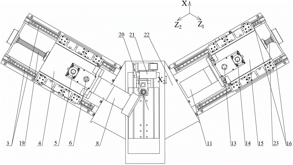
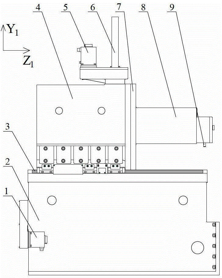
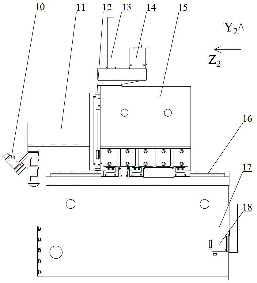
[0022] see Figure 1~5 , the embodiment of the present invention is provided with a grinding device, a polishing device, a movable online trimming device and a workbench device; the angle between the grinding device and the workbench device is 60°, and the angle between the polishing device and the workbench device is 60°.

[0023] Grinding device is provided with grinding device bed base 2, Z 1 Axis servo motor 1, Z 1 Shaft ball screw pair 19, Z 1 Axis guide rail 3 (there are 2 and set symmetrically), Y 1 Axis servo motor 5, Y 1 Shaft ball screw pair 6, Y 1 Shaft guide rail 7 (there are 2 and arranged symmetrically), grinding device column 4, main shaft support 8 and grinding wheel 9. Grinding device bed base 2 and grinding device column 4 pass Z 1 Axis rail 3 connected, Z 1 Axis ball screw 19 located in 2 root Z 1 Between the shaft...


PUM


Abstract

A grinding and polishing combined machining machine tool relates to a precision grinder and a polishing machine tool. The grinding and polishing combined machining machine tool comprises a grinding device, a polishing device, a movable on-line trimming device and a workbench device; the grinding device and the polishing device are respectively arranged on one side of the workbench device; the grinding device is provided with a grinding device tool body base, a Z1-axis servo motor, a Z1-axis ball screw pair, a Z1-axis guide rail, a Y1-axis servo motor, a Y1-axis ball screw pair, a Y1-axis guide rail, a grinding device column, a spindle carrier and a grinding wheel; the polishing device is provided with a polishing device tool body base, a Z2-axis servo motor, a Z2-axis ball screw pair, a Z2-axis guide rail, a Y2-axis servo motor, a Y2-axis ball screw pair, a Y2-axis guide rail, a polishing device column, a polishing device suspension arm and an air bag grinding head; the movable on-line trimming device is provided with a trimmer, an X2-axis guide rail, an X2-axis cylinder and a rotary platform; and the workbench device is provided with a workbench, a workbench tool body, an X-axis guide rail, an X-axis ball screw pair and an X-axis servo motor.

Description

technical field [0001] The invention relates to a precision grinding machine and a polishing machine tool, in particular to a compound grinding and polishing machine tool suitable for processing optical elements. Background technique [0002] Manufacturing is the pillar industry of the national economy, and grinding is an important field of manufacturing technology. It is the most effective and widely used basic technology for precision machining and ultra-precision machining in modern machinery manufacturing. [0003] The traditional ultra-precision grinding machine is used to process optical components. Although the processing precision is high, the processing efficiency is high, and the surface error is small, the processed optical components cannot meet the requirements of practical applications, and further polishing is required to make the processed optical components Optical components meet the precision requirements for practical applications (see references: Zhang N...

Claims


Application Information

Patent Timeline
IPC IPC(8): B24B13/00B24B47/12B24B53/06
Inventor 郭隐彪姜涛
Owner XIAMEN UNIV
Learn More