Rotary type magneto-rheological damper

A magneto-rheological damper, a rotary technology, applied in non-rotational vibration suppression, vibration suppression adjustment, etc., can solve problems such as enlargement, large axial size, failure to use the rotor end face, etc.

Inactive Publication Date: 2013-03-20
HEBEI UNIV OF TECH
View PDF6 Cites 16 Cited by
  • Summary
  • Abstract
  • Description
  • Claims
  • Application Information

AI Technical Summary

Problems solved by technology

Other rotary magneto-rheological dampers use the cylindrical surface of the rotor as the working surface, which is convenient to increase the axial and / or radial dimensions of the rotor to increase the output torque of the damper, but this structure fails to utilize the end surface of the rotor
In addition, in order to obtain a larger damping torque, a multi-disk magneto-rheological damper has also appeared. This kind of damper also uses the end face of the rotor as the working surface, and still has a relatively large axial dimension and a relatively complicated structure. insufficient

Method used


Image

  • Rotary type magneto-rheological damper
  • Rotary type magneto-rheological damper
  • Rotary type magneto-rheological damper

Examples


Embodiment Construction

[0014] Further describe the present invention below in conjunction with embodiment and accompanying drawing thereof.

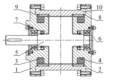
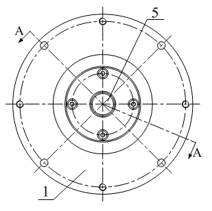
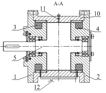
[0015] The rotary magneto-rheological damper designed by the present invention (referred to as the damper, see Figure 1-4 ), characterized in that the damper mainly includes a housing 10, a front end cover 1, a rear end cover 2, a front excitation coil 3, a rear excitation coil 4, a rotor 5, a bearing 6, a sealing ring 7, a sealing ring 8, and a magnetic isolation ring 9 and housing 10 .

[0016] The front end cover 1 and the rear end cover 2 of the damper of the present invention are located on both sides of the rotor 5, and the front end cover 1 and the rear end cover 2 are respectively connected with the shell 10 by screws to form a stator. Between the rotor 5 and the front end cover 1 and between the rotor 5 and the rear end cover 2, bearings 6 and sealing rings 7 are respectively placed; the front excitation coil 3 is wound in the front end cover 1, and...


PUM


Abstract

The invention discloses a rotary type magneto-rheological damper which is characterized in that the damper mainly comprises an outer shell, a front end cap, a back end cap, a front magnet exciting coil, a back magnet exciting coil, a rotor, a bearing, a sealing washer, seal rings and magnetic isolation rings. The front and back end caps are located at the two sides of the rotor and are respectively connected with the outer shell, forming a stator. The bearing and the sealing washer are respectively arranged between the rotor and the front and back end caps. The front and back magnet exciting coils are wound inside the front and back end caps. The magnetic isolation rings are respectively installed between the front and back end caps and the outer shell, and O-shaped seal rings are respectively arranged between the magnetic isolation rings and the outer shell as well as the front and back end caps. A sealed liquid charging hole is formed at the upper part of the outer shell, and magneto-rheological fluid is filled in a hollow cavity between the stator and the rotor. The front and back magnet exciting coils are wound in the same direction, with the tail ends being connected with each other in series and the head ends being loaded with power sources. The two magnet exciting coils form two parallel magnetic pathways which generate two magnetic fields in opposite direction, and the magnetic flux is generated by a single piece of magnet exciting coils.

Description

technical field [0001] The invention relates to electronic devices, in particular to a rotary magnetorheological damper using magnetorheological fluid as a medium. Background technique [0002] Rotary MR dampers work by filling their stator and rotor with a MR fluid with controlled yield stress. The working area of ​​the rotor is one of the main factors affecting the performance of the damper. At present, some rotary magnetorheological dampers use the end surface of the rotor as the working surface, and the damper usually has a large radial dimension. Other rotary magneto-rheological dampers use the cylindrical surface of the rotor as the working surface, which is convenient to increase the axial and / or radial dimensions of the rotor to increase the output torque of the damper, but this structure fails to utilize the end surface of the rotor . In addition, in order to obtain a larger damping torque, a multi-disk magneto-rheological damper has also appeared. This kind of d...

Claims


Application Information

Patent Timeline
Patent Type & Authority Applications(China)
IPC IPC(8): F16F9/53
Inventor 李军强王娟赵海文刘今越陈贵亮
Owner HEBEI UNIV OF TECH
Why Eureka
Try Eureka