
Non-pressure gasified liquid fuel combustor and combustion cooker

A liquid fuel and gasification fuel technology, applied in liquid heating fuel, burner, combustion method, etc., can solve the problems of air pollution, low combustion efficiency, waste of fuel, etc.

Active Publication Date: 2013-03-20
海内环能(北京)科技有限公司
View PDF6 Cites 3 Cited by
  • Summary
  • Abstract
  • Description
  • Claims
  • Application Information

AI Technical Summary

Problems solved by technology

At present, a few stoves using gasification combustion technology for liquid fuels have appeared on the market, but these gasification combustion stoves need to pressurize the fuel, and the fuel supply pressure is required to be at least about 0.1MPa, or even reach 0.6MPa Even higher, the requirements on the pressurization technology of the fuel and the pressurization device limit the application range of this type of combustion technology furnace
[0005] On the other hand, there are still some problems in the currently used gasification combustion technology, such as the complexity of the gasification device, unstable gasification, gasification with liquid, and the gasifier and its nozzles are prone to carbon deposits and blockages. Therefore, the gasification of liquid fuels The stability and durability of gasification combustion devices need to be improved, so over the years, alcohol-based liquid fuel gasification combustion stoves have not achieved due development, and most types of alcohol-based fuel stoves still remain in the direct combustion of liquid and atomization In the backward state of combustion, not only a blower is required, but also the combustion efficiency is low, which wastes fuel and pollutes the air

Method used


Image

  • Non-pressure gasified liquid fuel combustor and combustion cooker

Examples


Embodiment Construction

[0023] The specific implementation manners of the present invention will be described in detail below in conjunction with the accompanying drawings.

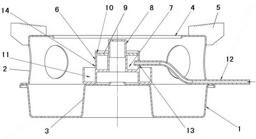
[0024] Such as figure 1 Shown is a schematic structural view of an embodiment of the pressureless gasification liquid fuel combustion stove of the present invention. The pressureless gasification liquid fuel burning stove of this embodiment comprises a pressureless gasification liquid fuel burner, a base 1 and a pan support 2, the cover of the pan support 2 is mounted on the base 1, and the base 1 is provided with a pressureless gasification liquid fuel burner. The burner mounting seat 3 of the fuel burner is provided with a combustion through hole 4 corresponding to the pressureless gasification liquid fuel burner on the pot support 2, and the outer edge of the combustion through hole 4 is provided with a pot mounting seat 5 for placing a pot.

[0025] The pressureless gasification liquid fuel burner of this embodiment include...


PUM


Abstract

The invention discloses a non-pressure gasified liquid fuel combustor which comprises a liquid fuel gasifying cup, wherein the liquid fuel gasifying cup is provided with a liquid fuel gasifying chamber with an upper opening. A heat conductive tube extending upwards is arranged in the middle of the liquid fuel gasifying chamber. A fire cover located at the upper opening of the liquid fuel gasifying chamber is arranged between the heat conductive tube and the liquid fuel gasifying chamber. A gasified fuel outlet is arranged on the fire cover and / or between the fire cover and the liquid fuel gasifying chamber. A preheating groove is arranged on the outer wall of the liquid fuel gasifying chamber, and the bottom of the preheating groove is lower than or equal to the bottom face of the liquid fuel gasifying chamber. The liquid fuel gasifying chamber is provided with a liquid fuel inlet connected with a liquid fuel inlet tube and an overflow opening for communicating the liquid fuel gasifying chamber with the preheating groove. The invention further discloses a non-pressure gasified liquid fuel combustion cooker which can gasify and combust the liquid fuel in a non-pressurizing condition.

Description

technical field [0001] The invention belongs to the technical field of burners, in particular to a liquid fuel burner capable of vaporizing and burning liquid fuel without pressurization and a liquid fuel burning stove using the burner. Background technique [0002] Alcohol-based liquid fuel is an economical, clean and environmentally friendly alternative energy source. Since alcohol-based fuel is liquid at normal temperature and pressure, it is more convenient to transport and store, safer than liquefied petroleum gas and natural gas, and burns without smoke. Since the alcohol-based fuel is a liquid fuel, the existing liquefied petroleum gas and natural gas stoves cannot be used to burn the alcohol-based liquid fuel, but special stoves using the alcohol-based liquid fuel must be developed. [0003] At present, the combustion technology using alcohol-based liquid fuel is still under development. There are many types of alcohol-based liquid fuel combustion devices that have b...

Claims


Application Information

Patent Timeline
Patent Type & Authority Applications(China)
IPC IPC(8): F23D11/00F23D11/36F23D11/44F24C5/02
Inventor 冯敏昌刘俊任建伟
Owner 海内环能(北京)科技有限公司
Learn More