Manual lifting deadweight loading device for landslide physical model test

A landslide physical model and loading device technology, which is applied in the direction of measuring devices, machine/structural component testing, instruments, etc., can solve the problem of fast, stable and continuous thrust loading requirements on the trailing edge of landslides, and the difficulty in the size and direction of landslide thrust. Accurate control, inconsistency of boundary conditions and other issues, to achieve the effect of easy movement and transportation, easy repair or replacement, and continuous loading angle

Active Publication Date: 2013-03-20
CHINA UNIV OF GEOSCIENCES (WUHAN)
View PDF10 Cites 15 Cited by
  • Summary
  • Abstract
  • Description
  • Claims
  • Application Information

AI Technical Summary

Problems solved by technology

[0005] (1) The thrust loading and control system of the trailing edge of the existing landslide physical model is often complex in structure and cumbersome in operation, and it is difficult to meet the requirements of fast, stable and continuous thrust loading on the trailing edge of the landslide;
[0006] (2) Although the existing method of manual loading can exert a stable force on the trailing edge of the landslide, it is difficult to accurately control the magnitude and direction of the thrust of the landslide, and the boundary conditions of the applied external force do not match the actual situation

Method used


Image

  • Manual lifting deadweight loading device for landslide physical model test
  • Manual lifting deadweight loading device for landslide physical model test
  • Manual lifting deadweight loading device for landslide physical model test

Examples


Embodiment Construction

[0037] Specific embodiments of the present invention will be described in further detail below in conjunction with the accompanying drawings.

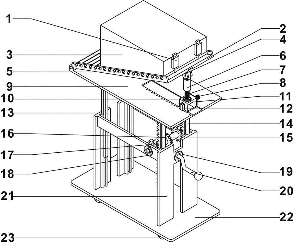
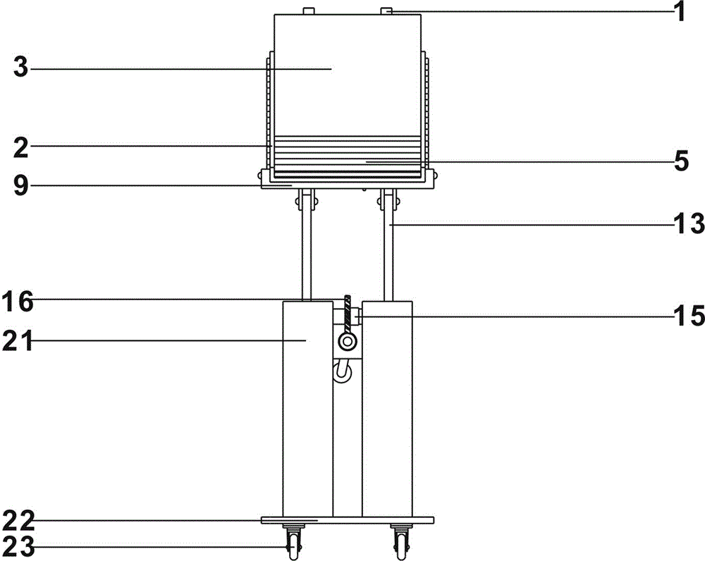
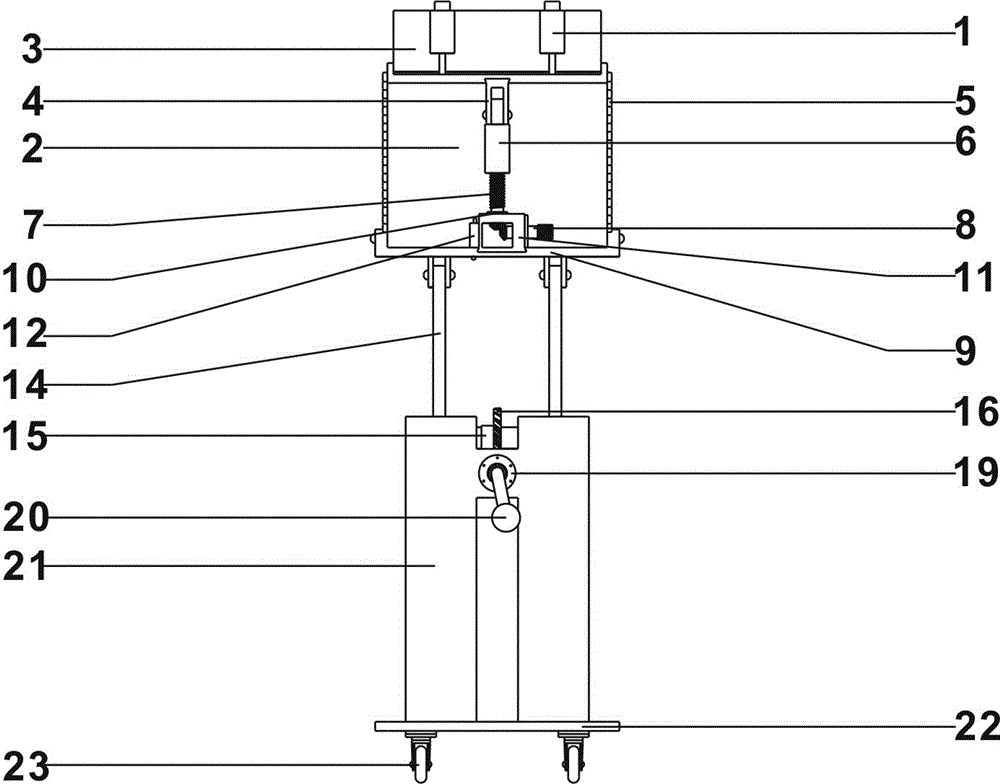
[0038] Such as Figure 1 to Figure 5 As shown, a manual lifting self-weight loading device for landslide physical model test of the present invention includes a bottom plate 22, a lifting mechanism, an angle adjustment mechanism and a thrust loading mechanism, specifically.

[0039] Base plate 22 below is provided with four road wheels 19, so that the movement of whole device.

[0040] The elevating mechanism is located on the base plate 22, and the elevating mechanism of the present embodiment includes a pair of intermeshing racks 14 and gears 17, transmission shafts 15, intermeshing worm wheels 16 and worm screws 24, rocking handles 20, a pair of support bars 13 and guides. Seat 21. The guide seat 21 is fixed on the base plate 22, and the front part and the rear part of the guide seat 21 are respectively provided with two vertical ...


PUM


Abstract

The invention discloses a manual lifting deadweight loading device for a landslide physical model test, which comprises a bottom plate, a lifting mechanism, an angle adjustment mechanism and a thrust loading mechanism, wherein the lifting mechanism is positioned on the bottom plate; the upper end of the lifting mechanism is connected with the angle adjustment mechanism; the lifting mechanism is used for driving the lifting of the angle adjustment mechanism; the angle adjustment mechanism comprises a support plate, a slide panel, a screw rod, a sleeve and a horizontal knob; the support plate is connected with the upper end of the lifting mechanism; the front end of the support plate is articulated with the front end of the slide panel; the screw rod is arranged at the rear end of the support plate in a supporting manner; the sleeve is sleeved at the upper part of the screw rod; the screw rod is connected with the sleeve by screw threads; the lower end of the screw rod is engaged with the end part of the horizontal knob by a bevel gear; the rotation of the horizontal knob can drive the screw rod to rotate; the top end of the sleeve is articulated with a slide connecting block; the slide connecting block is contacted with the rear part of the bottom surface of the slide panel; the thrust loading mechanism comprises a loading platform used for bearing weight; the bottom surface of the loading platform is slidingly matched with the top surface of the slide panel; and the loading platform can slide back and forth along the slide panel.

Description

technical field [0001] The invention belongs to the field of geological disaster model tests, in particular to a manual lifting type self-weight loading device for physical model tests of landslides. Background technique [0002] The landslide physical model test belongs to the category of geomechanics model test. Its theory originated from the structural model test established in the early 20th century. At present, it has gradually developed and extended to landslide field model test, landslide bottom friction model test, landslide frame model test, There are many research directions such as landslide centrifugal model test and landslide comprehensive model test. Among them, the landslide frame model test means that in the usual gravity field, the model is made by using similar materials that meet the similarity criterion in the frame model groove, and the deformation and various mechanical properties of the model are measured under the condition that the main boundary cond...

Claims


Application Information

Patent Timeline
Patent Type & Authority Applications(China)
IPC IPC(8): G01M99/00
Inventor 唐辉明易贤龙雍睿李长冬胡新丽马俊伟夏浩谭钦文
Owner CHINA UNIV OF GEOSCIENCES (WUHAN)
Why Eureka
Try Eureka