Thermal fatigue testing machine

A thermal fatigue and testing machine technology, used in material thermal analysis, measuring devices, instruments, etc., can solve problems such as unsatisfactory thermal fatigue test results, and achieve good cooling effect, obvious effect, and small temperature difference between inside and outside.

Inactive Publication Date: 2013-03-20
SHENYANG POLYTECHNIC UNIV
View PDF3 Cites 9 Cited by
  • Summary
  • Abstract
  • Description
  • Claims
  • Application Information

AI Technical Summary

Problems solved by technology

[0006] Purpose of the invention: The present invention provides a thermal fatigue testing machine, the purpose of which is to solve the problem of unsatisfactory thermal fatigue test results in the past

Method used


Image

  • Thermal fatigue testing machine
  • Thermal fatigue testing machine
  • Thermal fatigue testing machine

Examples


specific Embodiment approach

[0030] Detailed ways: The present invention will be further described below in conjunction with accompanying drawing:

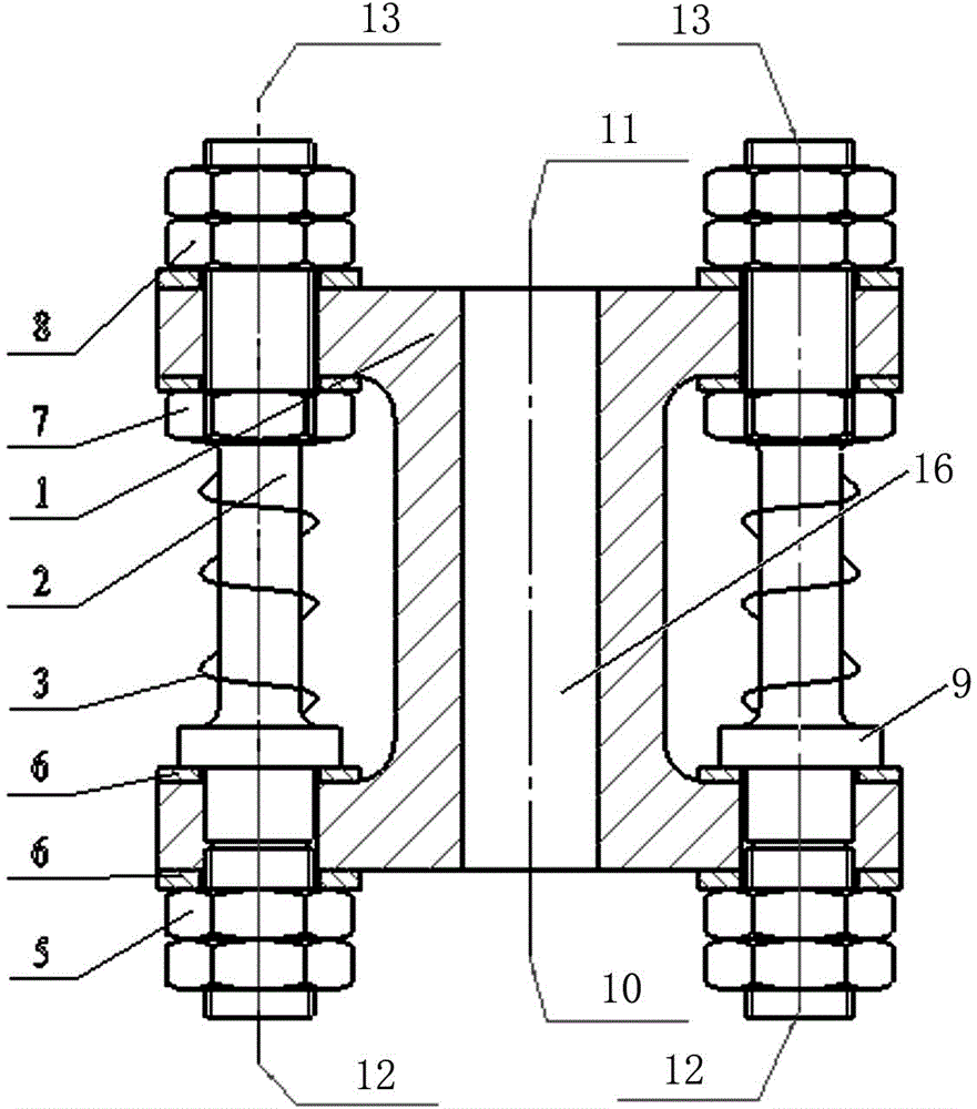
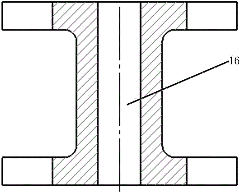
[0031] like figure 1 As shown, the present invention provides a thermal fatigue testing machine, which includes a support 1 and a thermal fatigue sample 2; the support 1 is a pillar structure with flanges up and down, and the main body of the support 1 is cylindrical. The center of the support 1 is provided with a support cooling channel 16, the upper part of the thermal fatigue sample 2 is stuck at the upper flange of the support 1 and the lower part is stuck at the lower flange of the support 1, and the outer wall of the thermal fatigue sample 2 is wound with an induction Heating coil 3.

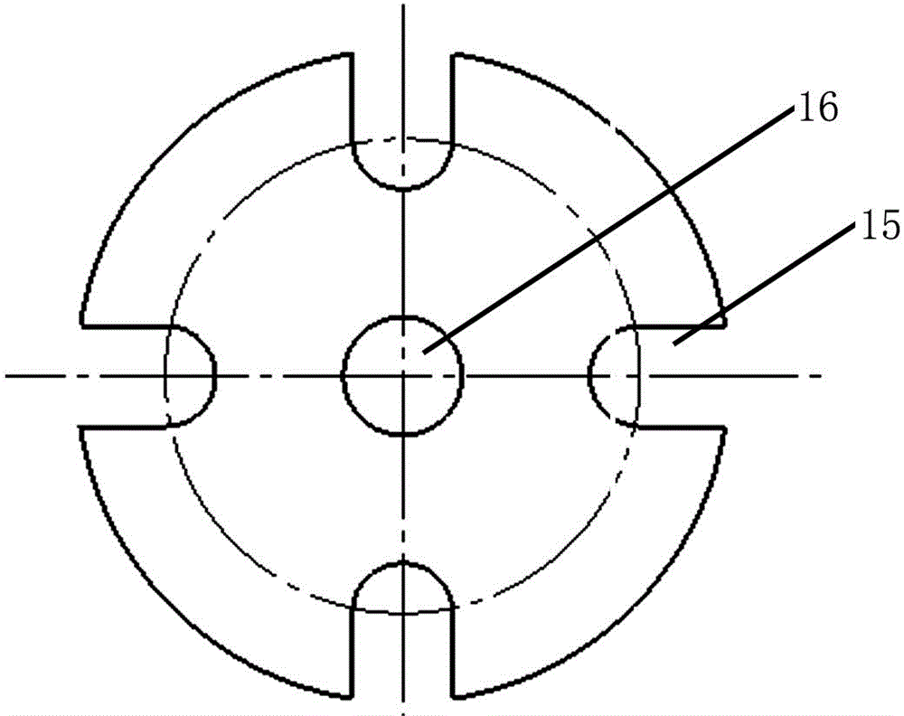
[0032] like Figure 4 As shown, the thermal fatigue sample 2 is a thin-walled cylindrical structure with a central hole, and the central hole is the sample cooling channel 14 .

[0033] The thermal fatigue sample 2 has a structure with external threads at both ends,...


PUM


Abstract

The invention provides a thermal fatigue testing machine which is characterized by comprising a support and a thermal fatigue testing specimen, wherein the support is of a support pillar structure with an upper flange and a lower flange; the center of the support is provided with a support cooling water channel; the upper part of the thermal fatigue testing specimen is clamped at the upper flange of the support, while the lower part of the thermal fatigue testing specimen is clamped at the lower flange of the support; and the outer wall of the thermal fatigue testing specimen is wound with an induction heating coil. The thermal fatigue testing machine is reasonable in structure, scientific in operation, remarkable in effects and suitable to popularization and application in the field of thermal fatigue testing.

Description

technical field [0001] The invention relates to material testing technology, in particular to a material thermal fatigue testing machine. Background technique [0002] When a component or material is subjected to temperature change (thermal cycle), cyclic stress or cyclic strain is generated because of its free expansion or contraction, which eventually leads to cracking and destruction, which is called thermal fatigue. [0003] Thermal fatigue damage widely exists in high-temperature equipment, power machinery, and precision electronic equipment. Examples: (1) During the normal operation of a nuclear power plant, when the high-temperature water in the main pipeline is mixed with the low-temperature water in the branch pipeline, the fluid boundary layer in the branch pipeline Periodic changes occur, resulting in periodic changes in the temperature of the branch pipes, causing thermal fatigue damage; (2) When the near-earth orbiter flies around the earth, the solar panels a...

Claims


Application Information

Patent Timeline
Patent Type & Authority Applications(China)
IPC IPC(8): G01N25/00
Inventor 闫明朱相军王明明李鸣金昊刘栋邹斌
Owner SHENYANG POLYTECHNIC UNIV
Why Eureka
Try Eureka