Sun identification device for photovoltaic power station

A technology for photovoltaic power plants and identification devices, applied in general control systems, control using feedback, instruments, etc., can solve the problem of high dependence of errors and accuracy on climate

Inactive Publication Date: 2013-03-20
STATE GRID CORP OF CHINA +1
View PDF0 Cites 3 Cited by
  • Summary
  • Abstract
  • Description
  • Claims
  • Application Information

AI Technical Summary

Problems solved by technology

[0002] Photovoltaic power generation is recognized as one of the important clean power generation methods in the future. Although it will encounter various problems in the development process, the industry is still optimistic about its prospects. The cost of photovoltaic power generation is one of the main bottlenecks in the large-scale development and application of pharmaceuticals. In order to reduce costs, the industry has adopted various technical means, such as technological improvement in the manufacturing field, improvement of cell efficiency, and thinning of thickness. These means focus on reducing the cost of photovoltaic modules. Another way is to increase the cost of photovoltaic The power generation efficiency of modules, such as concentrating photovoltaic power generation systems, tracking photovoltaic power generation systems, etc., among which tracking photovoltaic systems have been widely used in recent years due to the advantages of less hardware investment and easy implementation. In tracking photovoltaic power generation systems, The identification of the sun position is the most basic and critical link. If this system is inaccurate, it will not be able to maximize the power generation of the system. There are several ways to identify the sun position currently in use. The first is the photosensitive device type, which uses The photosensitive device directly detects the intensity of sunlight and sends signals to the controller through the sensor, and the controller drives the dual-axis tracker to realize the change of azimuth and altitude angles to track the po

Method used


Image

  • Sun identification device for photovoltaic power station
  • Sun identification device for photovoltaic power station
  • Sun identification device for photovoltaic power station

Examples


Embodiment Construction

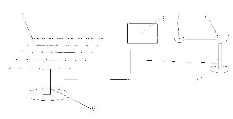
[0007] In order to explain the implementation of the present invention more fully, provide the implementation examples of the present invention, these implementation examples are only setting forth of the present invention, do not limit the scope of the present invention, the biaxial tracker involved in the present invention is in its structure and The application belongs to the known technology, and the design and manufacture are well known to ordinary technical personnel in the industry, and can be directly purchased in the market. The positioning method of the sun position is usually determined by two angles, the altitude angle and the azimuth angle. At the same time, different positions on the earth The position, altitude angle and azimuth angle are different. At the same position, the altitude angle and azimuth angle are also different at different times. The altitude angle of the sun refers to the angle between the sun's direct rays hitting the ground and the ground (wate...


PUM


Abstract

The invention relates to a sun identification device for a photovoltaic power station and belongs to the field of photovoltaic generation tracking systems. The device comprises a system computer provided with a module for positioning the sun by using a clock and a small double-shaft tracker controlled by the system computer, a small photovoltaic assembly is arranged on the small double-shaft tracker, an electric quantity detection device is arranged on the output of the small photovoltaic assembly and connected onto the system computer, the system computer first drives the small double-shaft tracker to perform primary position on the small photovoltaic assembly and collects electric quantity values on the electric quantity detection device, then the small double-shaft tracker drives the small photovoltaic assembly to move nearby the primary position, and the system computer collects electric quantity values at corresponding positions and selects the maximum electric quantity position as a new sun position for use of a large photovoltaic generating module after comparison with the electric quantity value at the primary position. The device is easy to popularize and apply to large photovoltaic generating modules.

Description

technical field [0001] The invention relates to a sun recognition device, in particular to a sun recognition device for a photovoltaic power station, belonging to the field of photovoltaic power generation tracking systems. Background technique [0002] Photovoltaic power generation is recognized as one of the important clean power generation methods in the future. Although it will encounter various problems in the development process, the industry is still optimistic about its prospects. The cost of photovoltaic power generation is one of the main bottlenecks in the large-scale development and application of pharmaceuticals. In order to reduce costs, the industry has adopted various technical means, such as technological improvement in the manufacturing field, improvement of cell efficiency, and thinning of thickness. These means focus on reducing the cost of photovoltaic modules. Another way is to increase the cost of photovoltaic The power generation efficiency of modules...

Claims


Application Information

Patent Timeline
IPC IPC(8): G05D3/12G05B13/04
Inventor 俎洋辉邹启群刘岩郝安民武勇
Owner STATE GRID CORP OF CHINA
Why Eureka
Try Eureka