Pipe joint cutting device

A technology of cutting device and pipe joint, applied in the field of pipe joint cutting device, can solve the problems of easy damage to drilling machine equipment, low production efficiency, etc., and achieve the effects of being convenient for large-scale use, high processing efficiency and good economic effect

Active Publication Date: 2013-03-27
SHANGHAI BOILER WORKS
View PDF6 Cites 6 Cited by
  • Summary
  • Abstract
  • Description
  • Claims
  • Application Information

AI Technical Summary

Problems solved by technology

This kind of pipe joint groove processing method is not only very easy to damage the drilling machine equipment, but also has low production efficiency

Method used


Image

  • Pipe joint cutting device
  • Pipe joint cutting device
  • Pipe joint cutting device

Examples


Embodiment

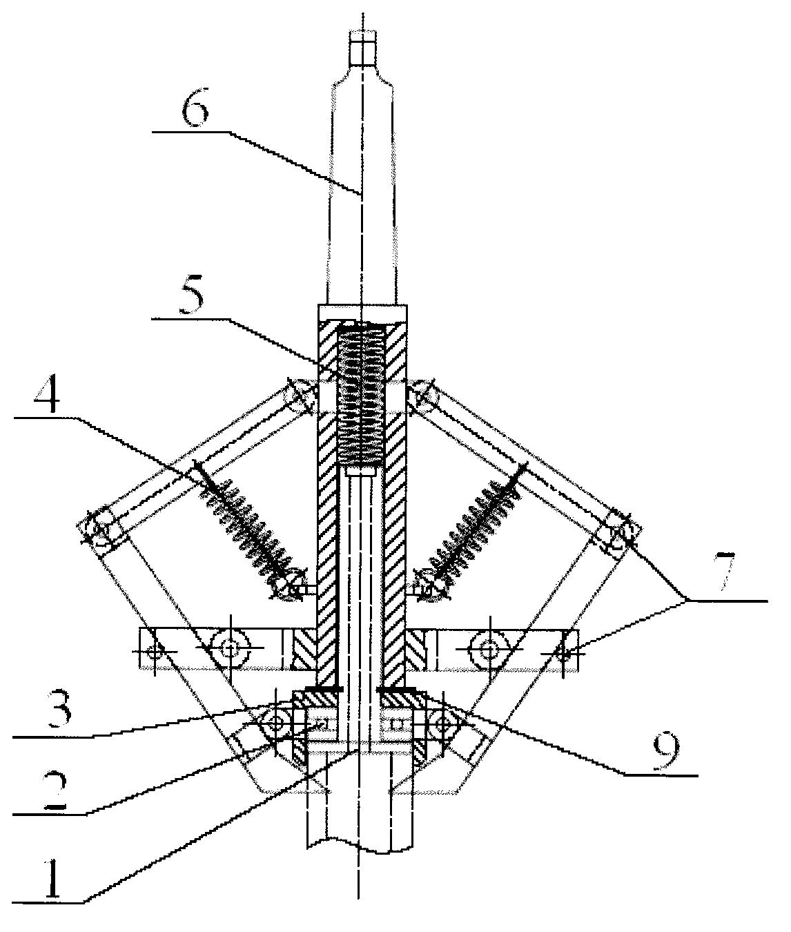
[0041] The present invention is a pipe joint cutting device, such as figure 1 Shown is a structural schematic diagram of a pipe joint cutting device. The contact device 1 passes through the capping device 3 and is connected with the lifting device 6 , the lifting device 6 is equipped with a tension spring 4 , and the lifting device 6 is equipped with a compression spring 5 .

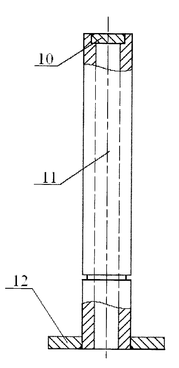
[0042] Such as figure 2 Shown is a schematic structural diagram of the contact device 1 . The contact device 1 includes a sealing plate 10, a top plate 12, and a sliding rod 11. The middle part of the sliding rod 11 is designed with a groove, and the top of the sliding rod 11 is embedded with the sealing plate 10, and is connected by welding, and the welding seam at the port is smoothed. The top plate 12 is aligned with the port at the bottom of the slide bar 11, and then connected by welding, and the weld seam is ground after welding.

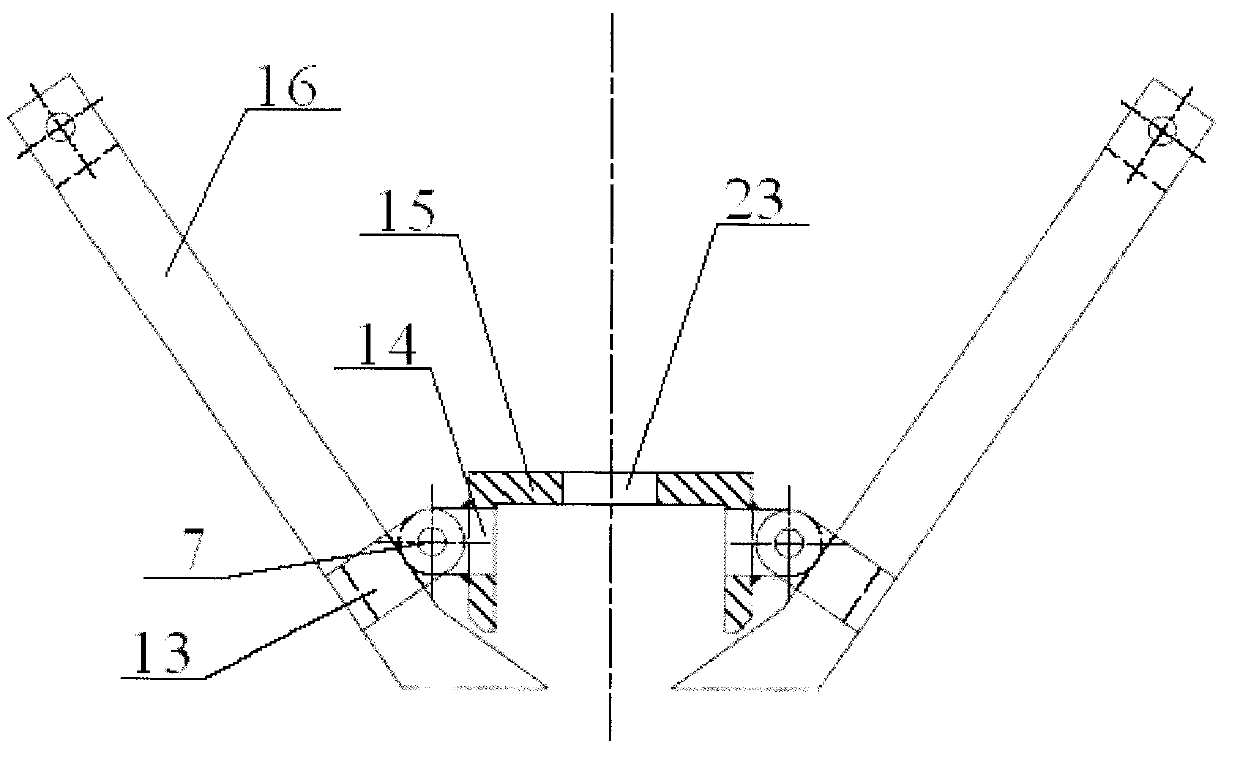
[0043] Such as image 3 Shown is a schematic structural view o...


PUM


Abstract

The invention discloses a pipe joint cutting device. The pipe joint cutting device is characterized by comprising a contact device, wherein the contact device penetrates through a gland device so as to be connected with a lifting device, an extension spring is arranged on the lifting device, and a compression spring is arranged in the lifting device. The pipe joint cutting device has the characteristics of high working efficiency, low manufacturing cost, small volume, good universality and the like.

Description

technical field [0001] The invention relates to a processing equipment for parts in a boiler, in particular to a pipe joint cutting device. Background technique [0002] At present, the hydraulic pressure test is required after the boiler header pipe joints and accessories are assembled, welded and heat treated. Therefore, after the hydrostatic test of the header, the hydraulic test margin at the end of the pipe joint needs to be cut off by manual gas cutting, and then the groove of the pipe joint is processed by using a drilling machine to drill and scrape. Among them, carbon steel and alloy steel pipe joints are divided into short pipe joints and long pipe joints. The design of the short pipe joint is: the port is in the form of internal boring, and it is necessary to install a welding hydraulic test sealing plate. The design of the long pipe joint is: rotary compression port form. The end face of the pipe joint is gas-cut by hand, the hardness of the gas-cut end face i...

Claims


Application Information

Patent Timeline
IPC IPC(8): B23D79/02B23D79/04
Inventor 陈力孙厚彬魏宏杰陆辉任艳明
Owner SHANGHAI BOILER WORKS
Why Eureka
Try Eureka