Eureka AIR delivers breakthrough ideas for toughest innovation challenges, trusted by R&D personnel around the world.

Bottle perform mold structure provided with bottle opening groove

A preform and mold technology, which is applied to the production of beverage filling bottles and the structure of preform molds, can solve the problems of affecting the appearance of the bottle, reducing the production efficiency of the mold, and difficult to discharge the exhaust completely, and achieving reliable demoulding and blank removal. , The effect of improving the exhaust effect and shortening the production cycle

Active Publication Date: 2013-03-27
GUANG DONG XING LIAN PRECISE MACHINERY
View PDF8 Cites 7 Cited by
  • Summary
  • Abstract
  • Description
  • Claims
  • Application Information

AI Technical Summary

Problems solved by technology

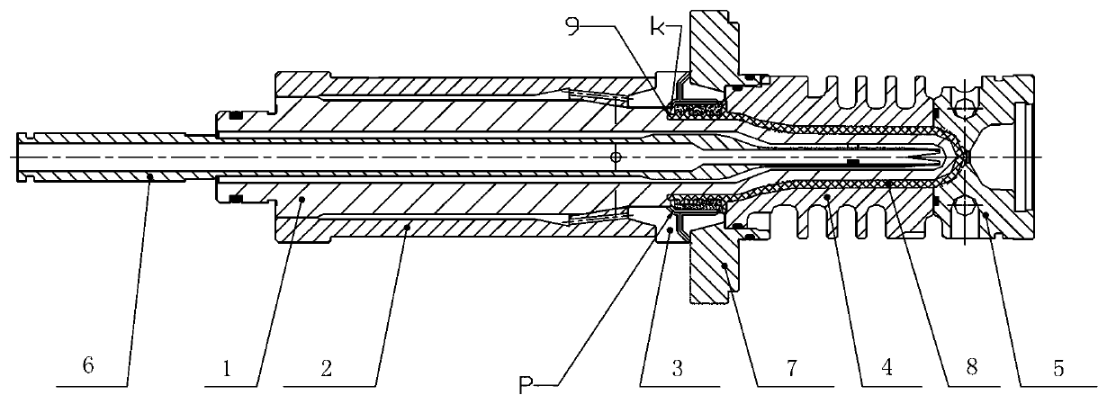
[0003] However, for the mold core structure designed with the bottle mouth groove 9, the exhaust in the bottle mouth groove 9 is difficult to be exhausted completely, and only a small part of the gas is released from the gap between the mold core and the lip contact end face K and the exhaust groove. P discharge
Therefore, it often occurs that the bottle mouth of the preform is not filled or has flashes, which affects the beauty of the bottle.
In order to ensure that the bottle mouth of the preform is filled, the required injection time is longer, which affects the production cycle of the mold, reduces the production efficiency of the mold, and makes injection molding difficult.

Method used


Image

  • Bottle perform mold structure provided with bottle opening groove
  • Bottle perform mold structure provided with bottle opening groove
  • Bottle perform mold structure provided with bottle opening groove

Examples


Embodiment Construction

[0029] In order to further understand the present invention, the present invention will be further described below in conjunction with the drawings and embodiments, but the embodiments of the present invention are not limited thereto.

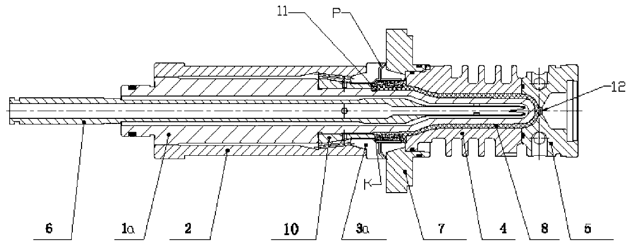
[0030] Such as image 3 , 4 As shown, a preform mold structure provided with a bottle mouth groove includes a mold core 1a, a mold core seat 2, a mold lip 3a, a mold cavity 4, a mold cavity bottom 5, a mold core cooling pipe 6, a mold cavity cover 7 and The mold core clamping ring 10; the mold core 1 is a hollow cylindrical structure, and the mold core 1a is provided with a core cooling pipe 6 in the hollow; the center of the mold core cooling pipe 6 is an inner hole, and the mold core cooling pipe 6 is mainly used for Pass cooling water to the mold cavity; outside the mold core 1a, from left to right, there are core base 2, mold core clamping ring 10, mold lip 3a, mold cavity 4 and mold cavity bottom 5; mold cavity 4, mold cavity A cavity is...


PUM

PropertyMeasurementUnit
diameteraaaaaaaaaa

Abstract

The invention discloses a bottle perform mold structure provided with a bottle opening groove. A mold core mode-locking ring of the bottle perform mold structure is a hollow cone-column structure, the inside of the hollow cone-column structure is cylindrical, one peripheral end is a cone structure, one end is a cylindrical structure, a through hole is arranged on a wall at the combing position of the cone structure and the cylindrical structure, an annular groove is processed on the inner side cylindrical face at the end portion of the cylindrical structure of the mold core mode-locking ring, and an air vent groove is formed at the step transition position of the annular groove and the mold core outer cylindrical face. A mold lip consists of two split oppositely-opening pieces, and one piece is provided with the air vent groove on the contact face of the two pieces. The air vent groove is divided into two branches, one branch is parallel to the axial direction of the mold lip, one end of the one branch is led to the contact end face of the mold core mode-locking ring and the mold lip, and a distance from the contact end face to the mold lip is 0.025-1mm. The bottle perform mold structure achieves multiple-channel air venting and is high in air venting speed. A bonding line is close to a bottle opening. The required opening distance of the mold lip is short in demolding, and demolding and perform fetching are reliable.

Description

technical field [0001] The invention relates to a preform mold, in particular to a preform mold structure provided with a bottle mouth groove, which is used for producing beverage filling bottles. technical background [0002] Insufficient filling of product raw materials and large internal stress often occur in mold trial and production. For these phenomena, when adjusting the parameters of the injection molding process (temperature, pressure, time, injection rate, etc.) cannot be solved, it is necessary to consider whether the mold gate is reasonable. When the problems of the injection molding process and the gate are eliminated, the venting of the mold is the most critical problem. The main means to solve this problem is to open the vent or increase the size of the vent. Most of the multi-cavity preform molds used in the bottle making industry are as figure 1 with figure 2 As shown, the molding parts assembly of the preform mold is mainly composed of a mold core 1, a ...

Claims


Application Information

Patent Timeline
Patent Type & Authority Applications(China)
IPC IPC(8): B29C45/26B29C45/34B29C45/64B29L31/56
Inventor 谢国基姜晓平董书生李伟民李柏青胡青春
Owner GUANG DONG XING LIAN PRECISE MACHINERY
Why Eureka
Eureka Blog
Learn More