
Abutting joint method of transporting device

A boarding bridge and frame technology, applied to ground installations, transportation and packaging, aircraft parts, etc., can solve problems such as potential safety hazards, poor flexibility and sealing, easy damage to the fuselage shell, etc., to prevent overloading and good sealing Effect

Active Publication Date: 2013-03-27
LIYANG TECH DEV CENT
View PDF9 Cites 2 Cited by
  • Summary
  • Abstract
  • Description
  • Claims
  • Application Information

AI Technical Summary

Problems solved by technology

The above two documents are still relatively single for the use of laser rangefinders
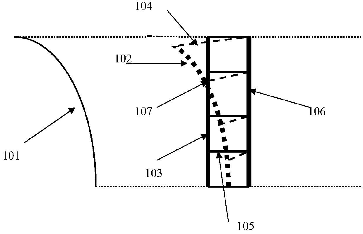
[0006] Therefore, the boarding bridges in the prior art generally have the following defects: due to the single force point of the energy storage device or the actuator, the flexible frame is difficult to adapt to various aircraft surface curvatures, and the flexibility and sealing are poor; The frame fits closely to the fuselage shell, and the force usually exerted is relatively large, which is easy to damage the fuselage shell. In addition, since the energy storage device or actuator usually starts to work after the awning device touches the fuselage shell, it is easy to cause damage to the fuselage shell by itself. Faults or system errors cause overload, which seriously damages the fuselage shell; there is a lack of real-time detection and alarm devices during the passenger boarding process, posing safety hazards

Method used


Image

  • Abutting joint method of transporting device
  • Abutting joint method of transporting device
  • Abutting joint method of transporting device

Examples


Embodiment Construction

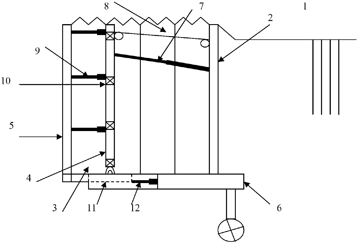
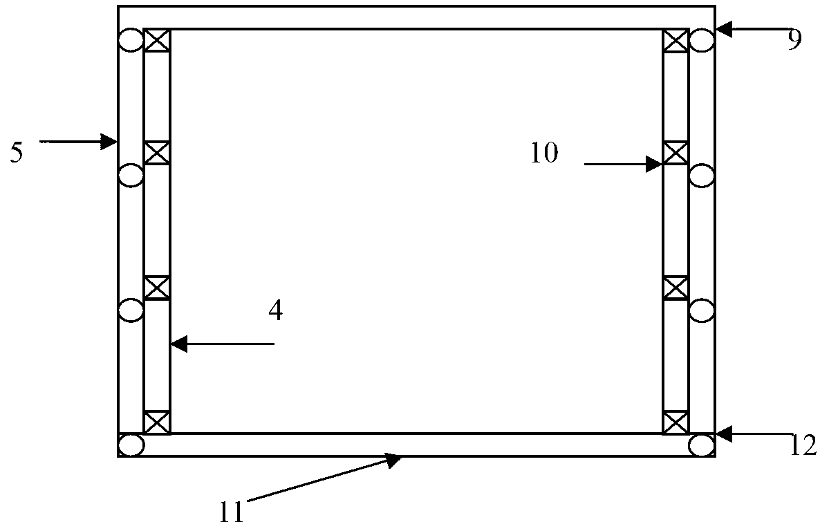
[0015] Refer to attached figure 1 , which partially shows a telescopic boarding bridge including rollers according to the present invention, which includes a bridge channel and an awning device 1, which includes a portal frame 2 and a docking frame 3, which is directly used In order to realize the docking of the canopy device 1 and the shell of the aircraft fuselage. The docking frame 3 includes a rigid frame 4 and a flexible frame 5 that will be in direct contact with the fuselage shell. The flexible frame 5 is made of flexible material, but the material has poor ductility, such as plastic. The flexible frame may further include cushioning materials, air cushions or elastically deformable tubes, etc. around the flexible frame. The canopy device further comprises a floor 6, wherein the floor is a retractable floor comprising a telescoping portion 11 by means of, for example, an actuator inside the floor, such as a hydraulic actuator. 12 to realize telescopic movement, the hy...


PUM


Abstract

The invention relates to an abutting joint method of a transporting device and provides a boarding bridge manipulation method. The method comprises the following steps of: starting laser range finders and measuring distances between a flexible frame and an airplane body, and temporarily stopping the boarding bridge moving close to the airplane when the boarding bridge extends and moves forwards towards the airplane in the vertical direction to further approach to the airplane to be subjected to abutting joint by a certain distance; controlling the flexible frame to deform by using an actuator and the distances measured by the plurality of laser range finders, so that the deformed flexible frame and a shell of the airplane body to be subjected to abutting joint have same surface curvature; continuously controlling the boarding bridge to move forwards, and braking the boarding bridge when the distance measured by the laser range finder at the front end of a floor reaches a preset value; and controlling a winding mechanism to release an energy accumulation device by a controller, so that an abutting joint frame is closely pressed to the shell of the airplane body. Due to utilization of the boarding bridge manipulation method, the sealability and safety are improved.

Description

technical field [0001] The invention relates to a docking method of a transport device, in particular to a method for manipulating a boarding bridge including a docking frame that can adaptively have a shape conforming to the curvature of the plane surface before docking with the plane. Background technique [0002] Airplane boarding bridge is a piece of airport equipment commonly used by modern passenger aircraft. They are used as the entrance for boarding, allowing passengers to enter the interior of the passenger aircraft from the terminal building. This type of boarding bridge usually has a canopy device at its end, which bridges the space between the boarding bridge and the aircraft, so as to protect the boarding personnel from the influence of bad weather conditions. [0003] Patent document CN100355628C discloses a sealing device for aircraft passenger ladders or aircraft boarding bridges, comprising a bellows tensioned above a connection floor, wherein the bellows ha...

Claims


Application Information

Patent Timeline
IPC IPC(8): B64F1/305
Inventor 狄睿狄春保
Owner LIYANG TECH DEV CENT
Learn More