Ball pin and ball joint

一种球头销、球头节的技术,应用在球头节领域,能够解决相互排斥等问题

Active Publication Date: 2013-03-27
ZF FRIEDRICHSHAFEN AG
View PDF4 Cites 9 Cited by
  • Summary
  • Abstract
  • Description
  • Claims
  • Application Information

AI Technical Summary

Problems solved by technology

[0006] Therefore, in summary, the problem of the prior art is that, according to the teachings known from the prior art, the nitriding of the ball studs, which is very necessary for corrosion protection on the one hand and the higher service life and wear on the other hand The case hardening required for protection is still mutually exclusive in one ball stud

Method used


Image

  • Ball pin and ball joint

Examples


Embodiment Construction

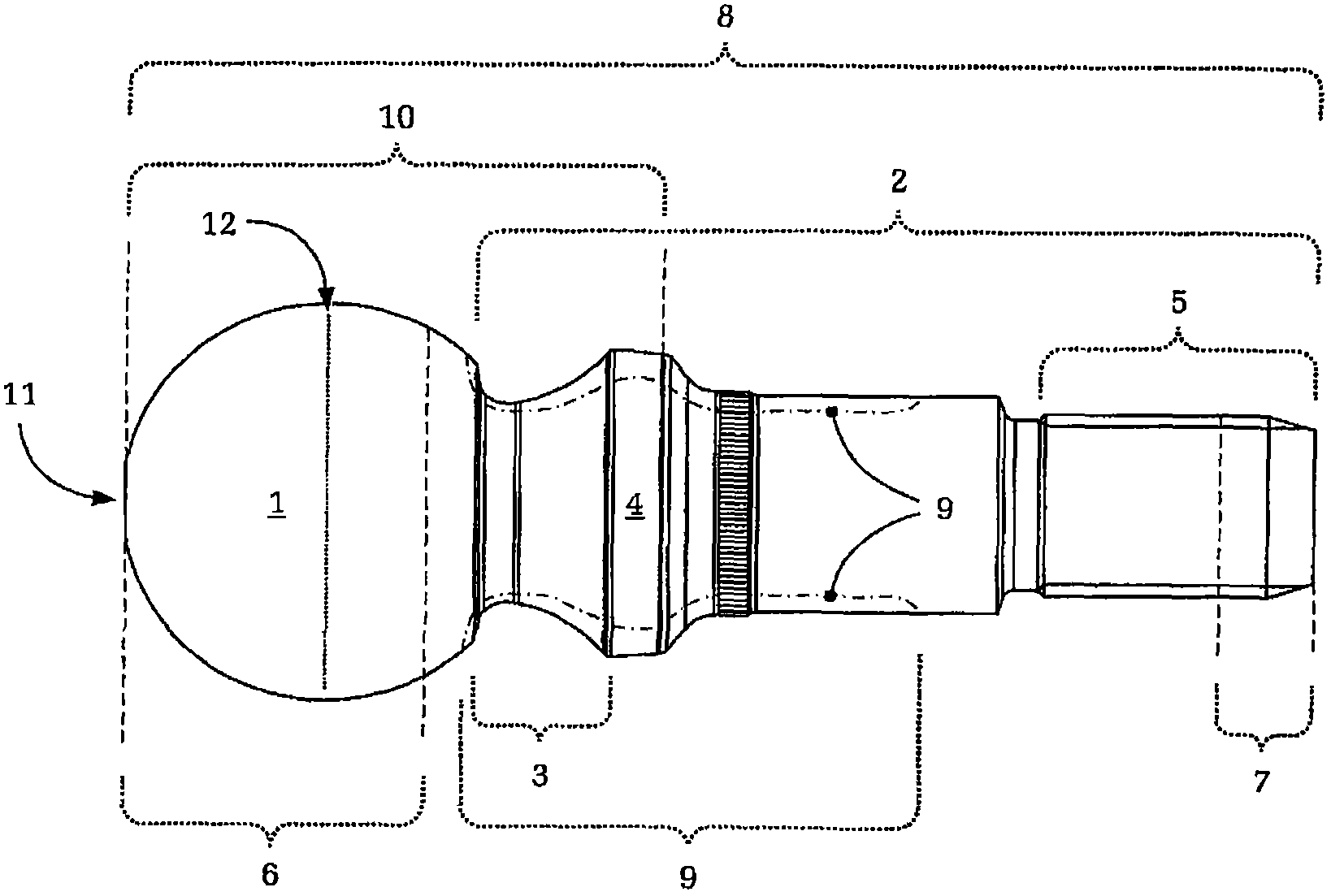
[0031] It can be seen from the figure that the ball stud has an articulation ball 1 , a shank area 2 , a neck area 3 , a sealing area 4 (for abutting against a sealing capsule) and a threaded area 5 .

[0032] The ball stud shown here is provided with a nitrided layer in the partial region 6 of the joint ball 1 extending from the dome 11 to the equator 12 and in the region 7 of the threaded end. Here, the nitrided layer in the regions 6 and 7 serves not only as usual for good corrosion protection, but also, as known to the applicant, in particular for protection against wear. The ball stud shown is therefore particularly suitable for high static initial loads and / or frequent operating periods with micro-movements, in which solid-body friction prevails between the ball stud and the spherical socket.

[0033] The illustrated embodiment of the ball pin also has an oxide layer, in particular an iron oxide layer, over its entire length or on the surface 8 . This oxide layer furthe...


PUM


Abstract

A ball joint with a ball pin and a steel ball pin with a joint ball (1). The ball joint and ball pin are suitable for use when, for example, solid-on-solid friction predominates under high static pre-loading or high operational loads and with small joint movements. A portion of the surface of the ball pin has surface layer hardening (9) in order to increase a fatigue strength of the ball pin. The ball pin and the ball joint, on portion of the ball pin without the any surface layer hardened, includes a nitrided layer (6) as wear protection. The ball pin and the ball joint provide an advantageous combination of high fatigue strength, good corrosion protection and high wear-resistance. The nitrided layer of ball joints, previously only regarded as improving corrosion protection, also functions as a wear protection. Thus, these ball pins overcome the mutual exclusion between surface layer hardening and nitriding.

Description

technical field [0001] The invention relates to a ball stud made of steel according to the preamble of claim 1 and a ball stud according to the preamble of claim 2 . Background technique [0002] In the case of bearing joints under static initial loads, for example in the chassis area of ​​motor vehicles, the friction system of the joint under certain conditions (for example standstill times or motorway driving with only minimal joint movements) Subject to particularly high loads, which can lead to premature wear or failure of the hinge. In connection with this, the lubricant located in the ball joint in this state (due to the extremely small joint movements are always accompanied by high loads) partly escapes from the contact area between the ball stud and the bearing sleeve. was squeezed out. As a result, the mixed friction between liquid friction and solid friction that is always present in ball joints is shifted more strongly towards solid friction, with correspondingl...

Claims


Application Information

Patent Timeline
Patent Type & Authority Applications(China)
IPC IPC(8): F16C11/06C23C8/04C23C8/10C23C8/24C23F17/00
CPCF16C2223/10F16C11/0604F16C2223/14F16C11/06Y10T403/32631
Inventor D·阿达姆克兹克W·克莱纳K·帕佩W·奥伊勒里希M·雷希泰恩T·维格曼M·海德曼J·克鲁塞J·塔博尔R·雅尔佩U·舍夫兹克
Owner ZF FRIEDRICHSHAFEN AG
Why Eureka
Try Eureka