General coded electric automobile shifting controller
A technology of electric vehicle and motor drive control, applied in the direction of transmission control, components with teeth, belt/chain/gear, etc., which can solve the waste of time and money, unfavorable energy saving and environmental protection, gear shift control mode and realization of control Problems such as messy parts, to achieve the effect of easy replacement, convenient controller matching, and good versatility
- Summary
- Abstract
- Description
- Claims
- Application Information
AI Technical Summary
Problems solved by technology
Method used
Image
Examples
Embodiment 2
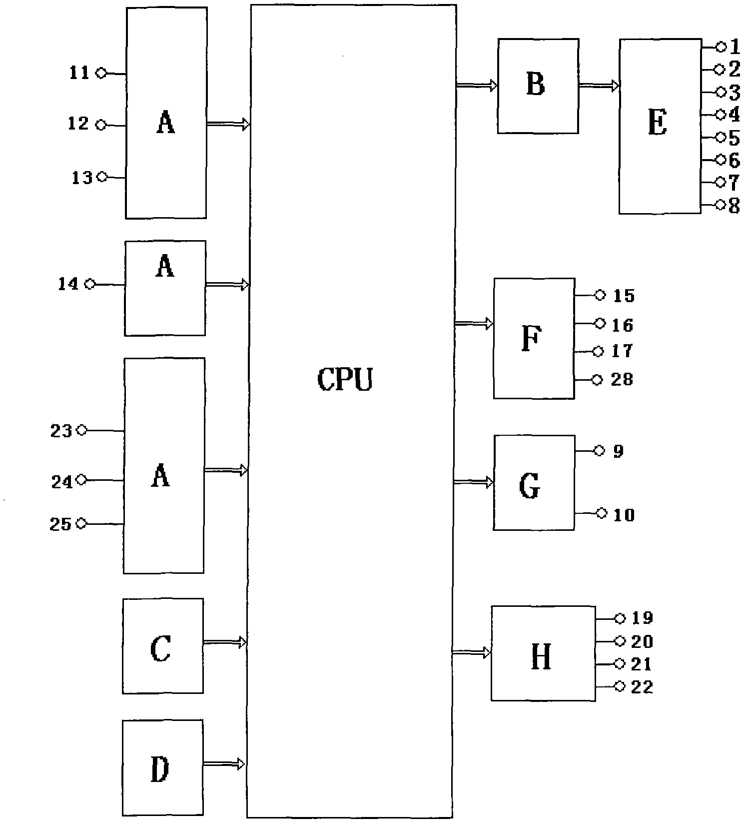
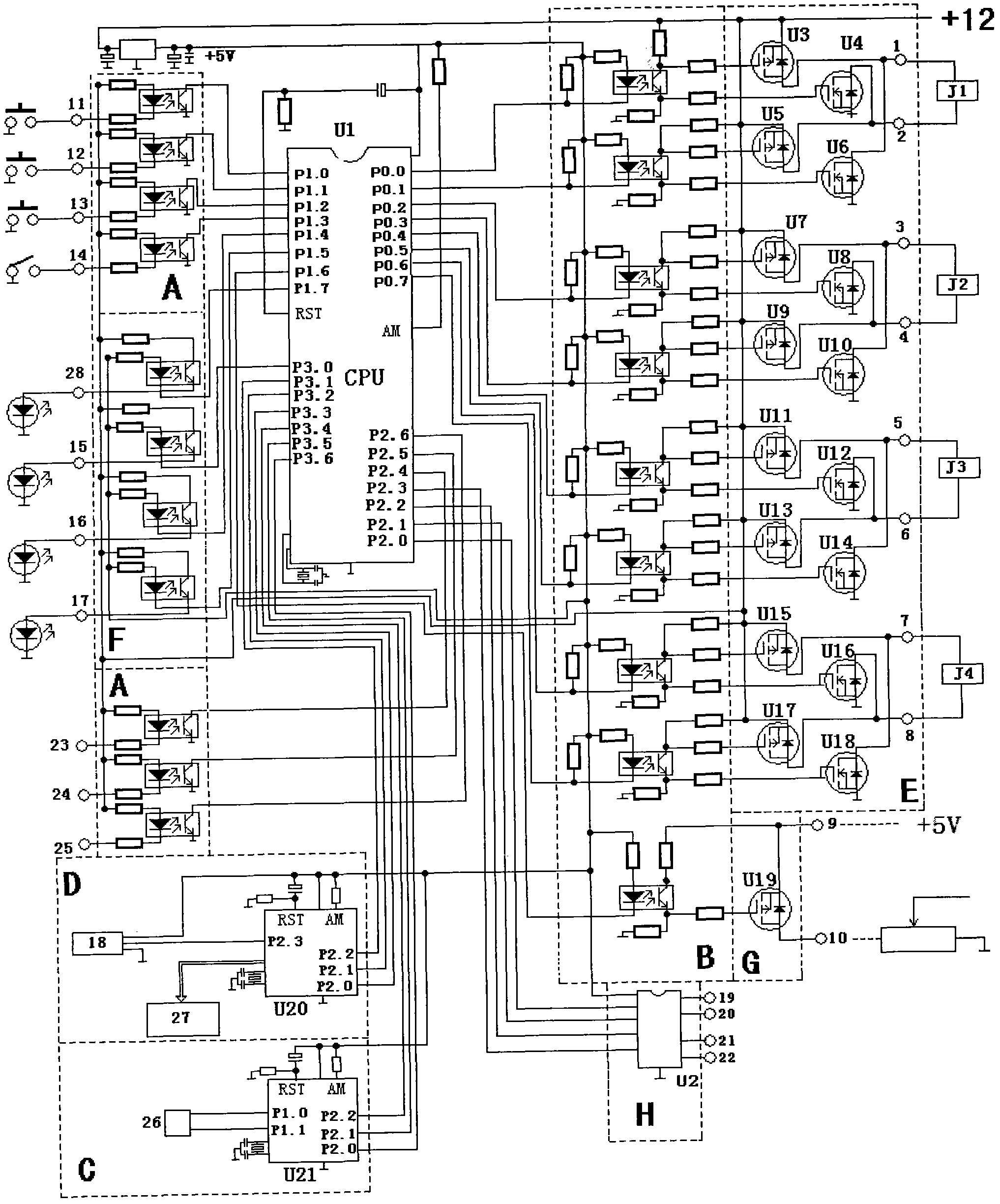
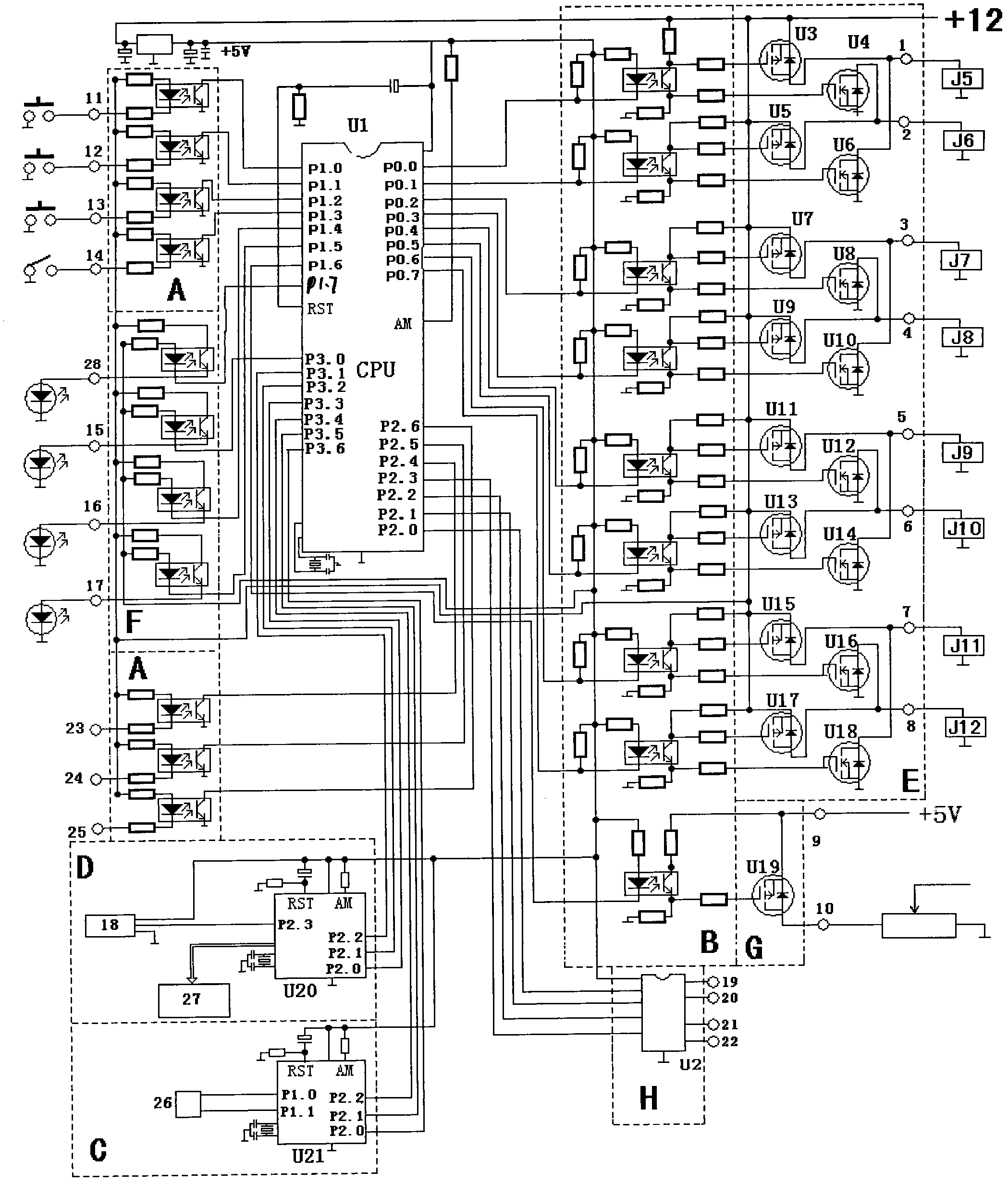
[0019] Embodiment two: image 3 Shown is the electrical schematic diagram of this general coded electric vehicle shift controller controlling 8 ordinary electromagnetic relays to complete the shift task. The part enclosed by the dotted line in the figure and the capital letters in the dotted line indicate that the circuit of this part is a block diagram The schematic diagram inside the corresponding box, 1 to 8 are the gear shift control output terminals, J5 to J12 are 8 ordinary electromagnetic relays installed outside the general coded electric vehicle shift controller, and the gears of the car are reversed. The voltage polarity requirements of each output terminal of the gear controller are stipulated as follows: in the first gear, the relays J5, J8, J9, and J11 are pulled in, and the relays J6, J7, J10, and J12 are released, that is, 1+, 2-, 3-, 4+ , 5+, 6-, 7+, 8-, when in second gear, relays J6, J7, J9, J12 pull in, J5, J8, J10, J11 release, that is, 1-, 2+, 3+, 4-, 5 +...
Embodiment 3
[0022] Embodiment three: Figure 4 Shown is the electrical schematic diagram of this general coded electric vehicle shift controller controlling two stepper motors to complete the automatic shift task. The part enclosed by the dotted line in the figure and the uppercase letters in the dotted line represent the circuit of this part It is the schematic diagram inside the corresponding box in the block diagram. M1 and M2 are two stepper motors installed outside the general coded electric vehicle shift controller to drag the gear lever for mechanical movement. M1 is used to execute the X-axis direction M2 is used for dragging in the Y-axis direction, QD1 and QD2 are the drivers of M1 and M2 respectively, the requirements for the running track of the gear lever of the automotive mechanical gearbox and the relative positions of each gear are as follows Figure 5 As shown, the relationship between the steering direction and the coordinate value of the stepping motor is specified as f...
PUM
 Abstract
Description
Claims
Application Information
 - R&D
- Intellectual Property
- Life Sciences
- Materials
- Tech Scout
- Unparalleled Data Quality
- Higher Quality Content
- 60% Fewer Hallucinations
Browse by: Latest US Patents, China's latest patents, Technical Efficacy Thesaurus, Application Domain, Technology Topic, Popular Technical Reports.
© 2025 PatSnap. All rights reserved.Legal|Privacy policy|Modern Slavery Act Transparency Statement|Sitemap|About US| Contact US: help@patsnap.com


