Optical fiber sensor-based natural gas pipeline leakage monitoring system

A natural gas pipeline, optical fiber sensing technology, applied in pipeline systems, measuring devices, gas/liquid distribution and storage, etc., can solve the problems of high false alarm rate, low sensitivity, and easy to be affected by environmental factors.

Active Publication Date: 2015-05-13
BC P INC CHINA NAT PETROLEUM CORP +1
View PDF11 Cites 0 Cited by
  • Summary
  • Abstract
  • Description
  • Claims
  • Application Information

AI Technical Summary

Problems solved by technology

[0012] In view of the problems of low sensitivity, high false alarm rate, and susceptibility to environmental factors in the above-mentioned types of leak detection and monitoring technologies, the present invention provides a high-sensitivity quasi-distributed leak vibration monitoring system based on optical fiber sensing. Sensitivity sensors make it possible to detect in time the primary stage of leakage such as microleakage and seepage in the pipeline, and combine the time domain and frequency domain characteristics of leakage events to effectively reduce the false alarm rate of the system caused by interference. This technical solution overcomes the The poor accuracy of the previous monitoring technology and the lack of complex installation process enable relevant maintenance personnel to take timely countermeasures to avoid causing greater security incidents

Method used


Image

  • Optical fiber sensor-based natural gas pipeline leakage monitoring system
  • Optical fiber sensor-based natural gas pipeline leakage monitoring system
  • Optical fiber sensor-based natural gas pipeline leakage monitoring system

Examples


Embodiment Construction

[0078] The present invention will be further described in conjunction with the accompanying drawings and embodiments, but the protection scope of the present invention should not be limited thereby.

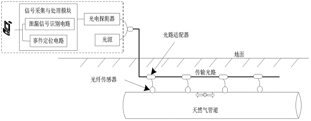
[0079] Embodiment. The composition of this example is as figure 1As shown, a fiber optic sensor is installed on the pipeline body every 1.5km, and a total of 10 sensors are installed. The first 5 sensors and the last 5 sensors form a sensor group respectively, and all fiber optic sensor groups share one fiber in the transmission cable with the The light source connection of the system is used as a launch fiber, and each fiber sensor group uses one fiber in the transmission cable to connect to the system photodetector as a return fiber; the output terminal of the photodetector includes the functions of leakage signal identification and event location The signal acquisition and processing module, the output of the signal acquisition and processing module is connected to the microco...


PUM


Abstract

The invention discloses an optical fiber sensor-based natural gas pipeline leakage monitoring system. The optical fiber sensor-based natural gas pipeline leakage monitoring system comprises an optical path system and a circuit. optical fiber sensors are arranged on a pipeline body at certain intervals; a plurality of adjacent optical fiber sensors form an optical fiber sensor group; the optical fiber sensor groups are connected with a light source through one transmitting optical fiber; each optical fiber sensor group is connected with an photoelectric detector through a return optical fiber; the output of the photoelectric detector is connected with a signal acquisition and processing module with leakage signal identifying and event positioning functions; and the output of the signal acquisition and processing module is connected with a microcomputer through an external interface. By the method and the system, the flexibility is high; and the positioning accuracy is high.

Description

technical field [0001] The invention is a natural gas pipeline leakage monitoring system based on optical fiber sensing. It involves the measurement of mechanical vibration, the measurement of impact and the technical field of piping system. Background technique [0002] At present, the total length of pipelines built in the world has reached 2.5 million kilometers, which has surpassed the total mileage of railways and has become the main mode of energy transportation in the world. Oil transportation in developed countries and oil-producing regions in the Middle East has all realized pipelines. my country's pipelines have also developed rapidly in recent years, with a total length of more than 70,000 kilometers. A large energy pipeline network has initially formed across the east, west, north and south, covering the whole country, and connecting overseas. Pipeline transportation has become the deployment of strategic energy such as oil and gas. The main method of delivery. ...

Claims


Application Information

Patent Timeline
Patent Type & Authority Patents(China)
IPC IPC(8): G01H9/00F17D5/02
Inventor 张金权王小军王飞刘素杰崔海龙任培奎刘春平黄现玲彭妍赵敏琴
Owner BC P INC CHINA NAT PETROLEUM CORP
Why Eureka
Try Eureka