Ultrasonic testing method for bonding quality of coated steel sheet and rubber

A technology of coated steel plate and detection method, which is applied in the direction of using sound wave/ultrasonic wave/infrasonic wave to analyze solids, etc., and can solve the problems of steel plate rubber bonding quality detection that cannot be coated

Active Publication Date: 2013-03-27
XIAN AEROSPACE CHEM PROPULTION PLANT
View PDF4 Cites 34 Cited by
  • Summary
  • Abstract
  • Description
  • Claims
  • Application Information

AI Technical Summary

Problems solved by technology

[0008] In order to overcome the deficiency in the prior art that the coated steel plate cannot be inspected for rubber bonding quality, the present invention proposes an ultrasonic detection method for the bond between coated steel plate and rubber

Method used


Image

  • Ultrasonic testing method for bonding quality of coated steel sheet and rubber
  • Ultrasonic testing method for bonding quality of coated steel sheet and rubber
  • Ultrasonic testing method for bonding quality of coated steel sheet and rubber

Examples


Embodiment 1

[0043] In this embodiment, the steel plate material to be tested is 30GrMnSiA, and the ultrasonic testing surface is sprayed with 0.4mm epoxy resin coating.

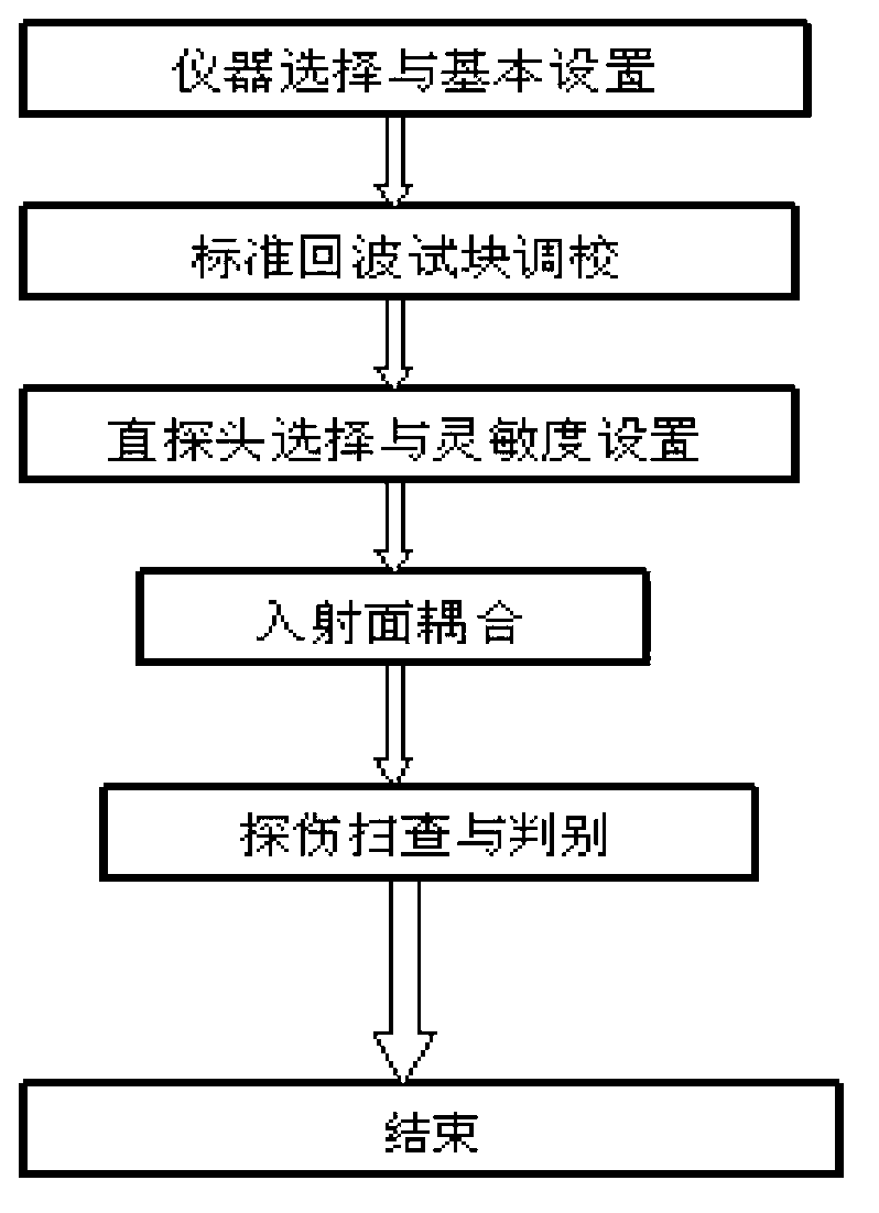
[0044] The specific process is:

[0045] Step 1: Ultrasonic detector selection and setting

[0046] The A-type pulse reflection ultrasonic detector is selected. In this embodiment, the CTS-23 pulse reflection ultrasonic detector commonly used in the industry is selected in order to generate pulsed ultrasonic waves and display real-time echo signals.

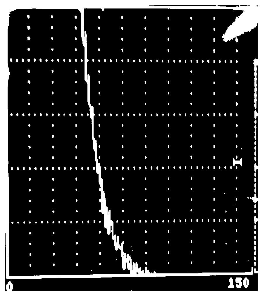
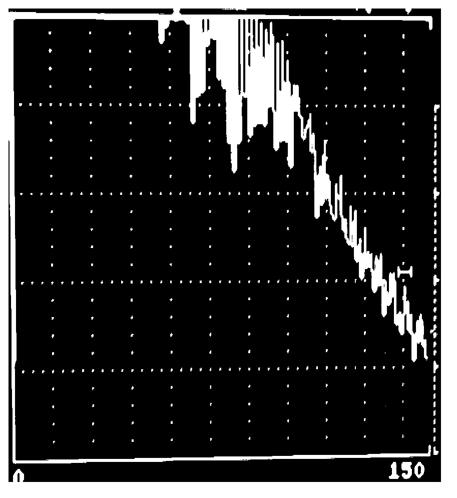
[0047] In order to make the ultrasonic detector display multiple echoes horizontally during the scanning process, the parameters of the pulse reflection ultrasonic detector are:

[0048] Detection mode: full wave; working mode: single probe spontaneous self-reception;

[0049] Suppression: Off; Scan Depth: 150mm.

[0050] Transmit intensity: minimum; frequency band selection: medium; repetition rate: X 1 ;

[0051] Step 2: Calibration of standard echo test block

[00...

Embodiment 2

[0062] In this embodiment, the detected steel plate is D406A, and the ultrasonic detection surface is sprayed with 1.7mm epoxy resin coating.

[0063] The specific process is:

[0064] Step 1: Ultrasonic detector selection and setting

[0065] The A-type pulse reflection ultrasonic detector is selected. In this embodiment, the CTS-23 pulse reflection ultrasonic detector commonly used in the industry is selected in order to generate pulsed ultrasonic waves and display real-time echo signals.

[0066] In order to make the ultrasonic detector display multiple echoes horizontally during the scanning process, the parameters of the pulse reflection ultrasonic detector are:

[0067] Detection mode: full wave; working mode: single probe spontaneous self-reception;

[0068] Suppression: Off; Scan Depth: 100mm.

[0069] Transmit intensity: minimum; frequency band selection: medium; repetition rate: X 1 ;

[0070] Step 2: Calibration of standard echo test block

[0071] After the s...

Embodiment 3

[0081] In this embodiment, the steel plate material to be tested is 30GrMnSiA, and the ultrasonic testing surface is sprayed with 1.0mm epoxy resin coating.

[0082] The specific process is:

[0083] Step 1: Ultrasonic detector selection and setting

[0084] The A-type pulse reflection ultrasonic detector is selected. In this embodiment, the CTS-23 pulse reflection ultrasonic detector commonly used in the industry is selected in order to generate pulsed ultrasonic waves and display real-time echo signals.

[0085] In order to make the ultrasonic detector display multiple echoes horizontally during the scanning process, the parameters of the pulse reflection ultrasonic detector are:

[0086] Detection mode: full wave; working mode: single probe spontaneous self-reception;

[0087] Suppression: Off; Scan Depth: 150mm.

[0088] Transmit intensity: minimum; frequency band selection: medium; repetition rate: X 1 ;

[0089] Step 2: Calibration of standard echo test block

[00...


PUM

PropertyMeasurementUnit
diameteraaaaaaaaaa
thicknessaaaaaaaaaa
thicknessaaaaaaaaaa

Abstract

The invention relates to an ultrasonic testing method for bonding quality of a coated steel sheet and rubber. The method comprises the following steps: conducting horizontal progressive scanning testing through a CTS-23 type pulse reflecting type ultrasonic tester, and by taking that the echo amplitude at the tenth horizontal grid on the display screen of the ultrasonic tester reaches or exceeds the longitudinal scale by 10% as benchmark, judging the bonding quality between the steel sheet with a resin coating and rubber according to the wave change on the screen of the ultrasonic tester; when no echo height exists at the tenth horizontal grid of the display screen of the ultrasonic tester or the echo height is lower than the longitudinal scale by 10%, judging the bonding between the steel sheet at the scanned position and the interface of the rubber to be good; and when the echo height at the tenth horizontal grid of the display screen reaches or exceeds the longitudinal scale by 10%, judging debonding, namely the steel sheet at the scanned position and the interface of the rubber are bonded badly. According to the method, the determination on the good bonding and debonding of an insulating layer can be realized through echo amplitude, and precise quantification can be conducted to the debonding area.

Description

technical field [0001] The invention relates to the field of ultrasonic testing, in particular to an ultrasonic testing method for the bonding quality of a coated steel plate and rubber. Background technique [0002] At present, the main direction of domestic ultrasonic testing is still the detection of the internal physical properties of materials, and there are relatively few researches on the detection of material bonding properties. The relevant technical research and literature background can be classified as follows: [0003] (1) Combination of equipment invention and technology research: For example, the Institute of Acoustics of the Chinese Academy of Sciences on the multi-channel and multi-interface ultrasonic imaging detection technology and equipment for bonding the thermal insulation layer of solid rocket motors, Beijing University of Aeronautics and Astronautics on air-coupled ultrasonic testing technology and equipment, laser Ultrasonic testing technology and e...

Claims


Application Information

Patent Timeline
Patent Type & Authority Applications(China)
IPC IPC(8): G01N29/04
Inventor 白小平刘永盛刘宾黄伟健孙瑾皓张潇钟波蔺娜李云魏炳哲尹维璋
Owner XIAN AEROSPACE CHEM PROPULTION PLANT
Why Eureka
Try Eureka