
Railway axle phased array ultrasonic flaw detection self-adaptive scanning device

A technology of ultrasonic flaw detection and scanning device, which is applied in the direction of measuring device, material analysis using sound wave/ultrasonic wave/infrasonic wave, instrument, etc. It can solve the problems of economic loss of flaw detection, damage of probe and fixture, low detection efficiency, etc., and achieve guarantee Safety and stability, reducing friction, and protecting the safety of testing equipment

Active Publication Date: 2013-03-27
王黎 +5
View PDF6 Cites 22 Cited by
  • Summary
  • Abstract
  • Description
  • Claims
  • Application Information

AI Technical Summary

Problems solved by technology

At present, in the traditional ultrasonic flaw detection of train axles, the flaw detection of key parts such as the axle diameter, axle body, wheel seat, etc., often uses ultrasonic probes with fixed fixtures. For axles with different diameters and different parts of the same axle, different The ultrasonic probe fixture adapts to the change of the axle diameter, which brings inconvenience to the axle ultrasonic flaw detection and low detection efficiency; in addition, the traditional probe positioning driving force uses a motor or oil pressure to directly act on the ultrasonic probe fixture. In the case of excessive pressure or improper operation In this situation, probes and fixtures are often damaged, which threatens the safety of flaw detection and brings direct economic losses to flaw detection.

Method used


Image

  • Railway axle phased array ultrasonic flaw detection self-adaptive scanning device
  • Railway axle phased array ultrasonic flaw detection self-adaptive scanning device
  • Railway axle phased array ultrasonic flaw detection self-adaptive scanning device

Examples


Embodiment Construction

[0014] In order for those skilled in the art to better understand the technical solutions provided by the present invention, the following will be described in conjunction with specific embodiments.

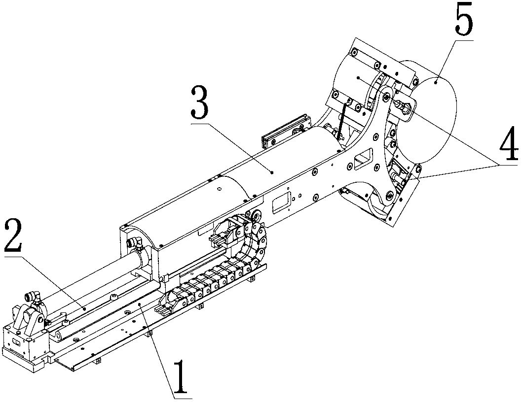
[0015] See Figure 1-Figure 4 , figure 1 It is a schematic diagram of the structure of the railway axle phased array ultrasonic flaw detection adaptive scanning device in the embodiment of the present invention when it is working, and the axle diameter of the axle in the figure is φ150mm; figure 2 It is a structural schematic diagram of the railway axle phased array ultrasonic flaw detection adaptive scanning device in the embodiment of the present invention when it is working, and the axle diameter of the dashed line axle in the figure is φ250mm; image 3 It is a structural schematic diagram of the telescopic drive device in the self-adaptive scanning device for phased array ultrasonic flaw detection of railway axles in the embodiment of the present invention; Figure 4 It is...


PUM


Abstract

The invention discloses a railway axle phased array ultrasonic flaw detection self-adaptive scanning device. Air compression force is adopted for driving an ultrasonic probe clamp, the gas flow rate and pressure can be regulated, the pressure is positioned in a floating manner, the clamp and the probe can be prevented from being damaged by excessive pressure, and the safety of detection equipment can be further protected; during the positioning process of the probe, according to the detected axle diameter, the single-axle rotational angle of the probe can be regulated in a self-adaptive manner for meeting the flaw detection requirements of railroad car axles with different diameters; and during the flaw detection process, the probe can move along a telescopic guide pole, the joint pressure between the probe and the surface of the axle can be regulated by extension and contraction of a pressure spring, the friction force between the surfaces of the probe and the axle can be reduced along with the rotation of rolling wheels, and the stability in coupling of the probe can be further ensured. The railway axle phased array ultrasonic flaw detection self-adaptive scanning device disclosed by the invention has the advantages of convenience in operation and strong applicability, and can ensure the safety and stability in probe positioning and improve the ultrasonic axle flaw detection efficiency.

Description

technical field [0001] The invention relates to the field of axle detection, in particular to an adaptive scanning device for railway axle phased array ultrasonic flaw detection. Background technique [0002] The scanning device of the axle ultrasonic detection probe is an important device for positioning and coupling of the probe in the ultrasonic flaw detection of the train axle. . The scanning device of the whole set of probes is the core component of the whole set of axle ultrasonic testing system. At present, in the traditional ultrasonic flaw detection of train axles, the flaw detection of key parts such as the axle diameter, axle body, wheel seat, etc., often uses ultrasonic probes with fixed fixtures. For axles with different diameters and different parts of the same axle, different The ultrasonic probe fixture adapts to the change of the axle diameter, which brings inconvenience to the axle ultrasonic flaw detection and low detection efficiency; in addition, the t...

Claims


Application Information

Patent Timeline
IPC IPC(8): G01N29/26G01N29/22
Inventor 彭建平张渝赵全轲高晓蓉王泽勇王黎杨凯彭朝勇李金龙李波房瑞晓
Owner 王黎
Learn More