Positioning support for micro drive motor

A micro-drive motor, positioning bracket technology, applied in electrical components, electromechanical devices and other directions, can solve the problems of low processing accuracy, can not be used for positioning, can not guarantee the bonding strength and other problems, to increase the impact resistance, improve the pass rate, Improves the effect of linear drive effects

Inactive Publication Date: 2013-03-27
深圳市光控数码光电有限公司
View PDF4 Cites 1 Cited by
  • Summary
  • Abstract
  • Description
  • Claims
  • Application Information

AI Technical Summary

Problems solved by technology

[0004] The difficulty brought about by this method is: in order to ensure the consistency of elastic deformation, it is necessary to strictly control the distance between the outer ring of the upper spring leaf and the outer edge of the lower spring leaf, and the distance between the inner ring of the upper spring leaf and the inner edge of the lower spring leaf; Since the inner ring of the upper spring is fixed on the top of the carrier, and the inner edge of the lower spring is fixed on the bottom of the carrier, both are fixed on the same part, so it is only necessary to ensure the processing accuracy of the carrier, that is, the inner ring of the upper spring and the inner ring of the upper spring can be easily controlled. The spacing between the inner edges of the lower shrapnel; however, the outer ring of the upper spring leaf and the outer edge of the lower shrapnel are respectively fixed on different parts, and the thicker part between the two is the magnet assembly, but the magnet assembly itself The processing accuracy is low and the error is large, so it cannot be used to locate the distance between the two; in addition, in traditional products, the outer ring of the upper spring and the upper gasket are fixed on the upper cover, and the installation position is limited by the accuracy and fixing method of the upper cover; The outer edge of the lower shrapnel is crimped and fixed on the base by the lower gasket, and its installation position is limited by the accuracy of the base and the fixing method; finally, the upper cover is glued and fixed on the base, so it is difficult to accurately ensure the distance between the outer ring of the spring leaf and the outer edge of the lower shrapnel That is, it is difficult to ensure that the elastic deformation produced by the upper spring and the lower spring just offsets the gravity produced by the carrier and the lens, thus affecting the linear drive effect
[0005] In addition, in traditional products, each magnet in the magnet assembly is fixed by glueing its outer wall adjacent to the side wall of the upper cover to the side wall of the upper cover. The bonding effect cannot be known through direct observation, so the bonding cannot be guaranteed. As a result, in the drop test, due to the severe impact force, once the bonding strength of the magnet is slightly poor, it will loosen or even fall off from the side wall of the upper cover, resulting in defective products, so its structure also needs improvement. place

Method used


Image

  • Positioning support for micro drive motor
  • Positioning support for micro drive motor
  • Positioning support for micro drive motor

Examples


Embodiment 1

[0023] (Embodiment 1, positioning bracket)

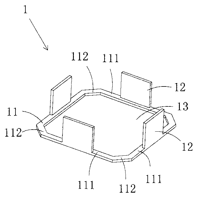
[0024] figure 1 It is a three-dimensional structural schematic diagram of the first structure of the positioning bracket of the present invention, showing the first specific embodiment of the positioning bracket of the present invention.

[0025] This embodiment is a positioning bracket for a micro drive motor, see figure 1 As shown, it includes a plate-shaped body 11 made of insulating plastic and four supporting bosses 12 protruding from the plate-shaped body for abutting on the outer ring of the upper spring leaf. The center of the plate-shaped body 11 A through hole (13) is provided, and each support boss 12 is located on the same side of the plate-shaped body.

[0026] The basic shape of the plate-like body 11 is a rectangular frame with four pressing edges 111. In this embodiment, the basic shape of each pressing edge 111 is a straight plate shape; at the center.

[0027] In practice, the number of the supporting bosses 12...

Embodiment 2

[0028] (Embodiment 2, positioning bracket)

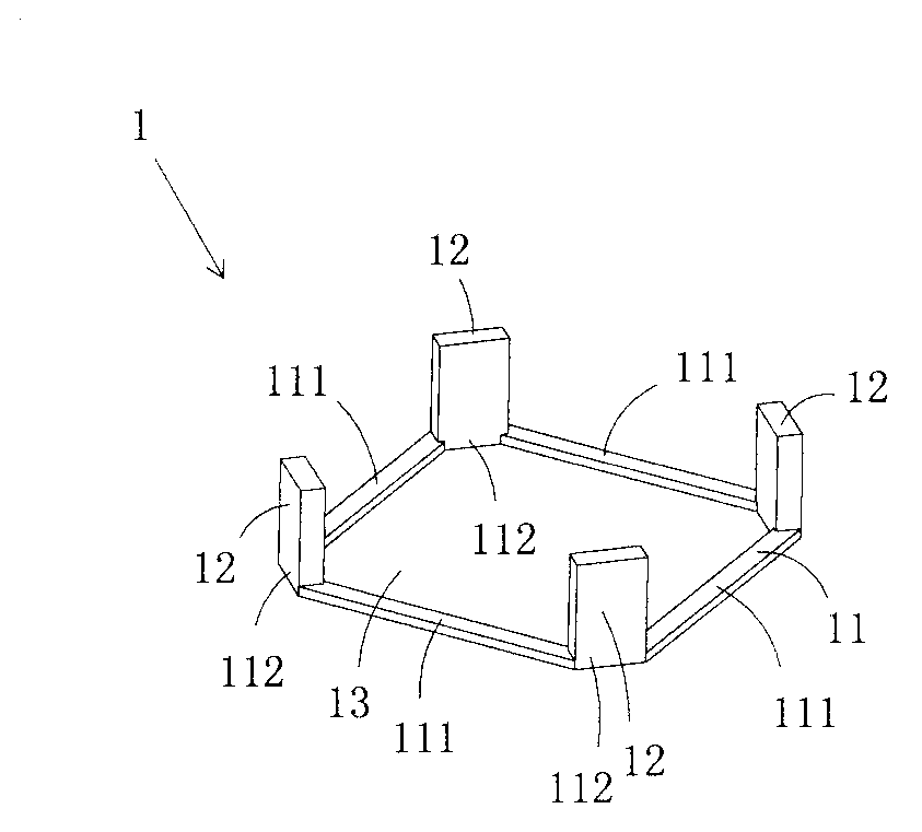
[0029] figure 2 It is a three-dimensional structural schematic diagram of the second structure of the positioning bracket of the present invention, showing the second specific embodiment of the positioning bracket of the present invention.

[0030] This embodiment is basically the same as Embodiment 1, the difference is: see figure 2 As shown, each supporting boss (12) is located at the junction of two adjacent pressing edges (111).

Embodiment 3

[0031] (Embodiment 3, positioning bracket)

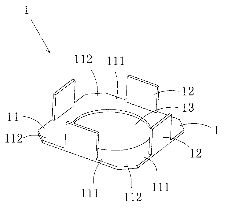
[0032] image 3 It is a three-dimensional structural schematic diagram of the third structure of the positioning bracket of the present invention, showing the third specific embodiment of the positioning bracket of the present invention.

[0033] This embodiment is basically the same as Embodiment 1, the difference is: see image 3 As shown, the basic shape of each blank 111 and the plate-shaped body 11 formed by their combination is different from that of Embodiment 1. In this embodiment, the inner edge of each blank 111 is arc-shaped, and all blanks 111 are enclosed to form A circular hole; the shape of the through hole 13 in Embodiment 1 is close to a rectangle.

[0034] In practice, the shape of the through hole 13 can be various, it can be regular shape or irregular shape, it only needs to be able to crimp and fix the outer edge of the circumscribed lower shrapnel without hindering the circumscribed The wire spring of the lo...


PUM


Abstract

The invention discloses a positioning support for a micro drive motor. The positioning support comprises a platy body and a plurality of support bosses, the a through hole is arranged at the center of the platy body, the support bosses projecting from the platy body are used for butting against an outer ring of an external upper spring piece, and each support boss is positioned on the side as same as the platy body. The positioning support is capable of effectively controlling the space between the outer ring of the upper spring piece and the outer edge of a lower spring piece, and accordingly linear drive effect is improved.

Description

technical field [0001] The invention belongs to the technical field of micro-motor structure design, and in particular relates to a positioning bracket for a micro-drive motor and a micro-drive motor. Background technique [0002] Micro camera devices have been widely used in mobile phones and notebook computers, and the micro drive motors (also called lens drive motors) therein are getting smaller and smaller. [0003] A traditional miniature drive motor generally includes an upper cover, an upper gasket, an upper spring sheet, a lens carrier, a magnet assembly, a coil assembly, a lower gasket, a lower spring assembly and a base. The traditional upper cover is made of magnetically permeable material, and includes a top wall and a side wall connected to the top wall, and a light-transmitting hole is arranged in the center of the top wall. The upper spring sheet includes an outer ring, an inner ring and a wire spring connecting the outer ring and the inner ring; the outer ri...

Claims


Application Information

Patent Timeline
IPC IPC(8): H02K33/18
Inventor 胡小青
Owner 深圳市光控数码光电有限公司
Why Eureka
Try Eureka