

Metal nanoparticle paste, electronic component assembly using metal nanoparticle paste, LED module, and method for forming circuit for printed wiring board
A technology of metal nanoparticles and atoms, applied in printed circuits, printed circuits, electric solid devices, etc., to achieve high reflectivity, excellent reflectivity, excellent reflectivity and thermal conductivity
- Summary
- Abstract
- Description
- Claims
- Application Information
AI Technical Summary
Problems solved by technology
Method used
Image

Examples
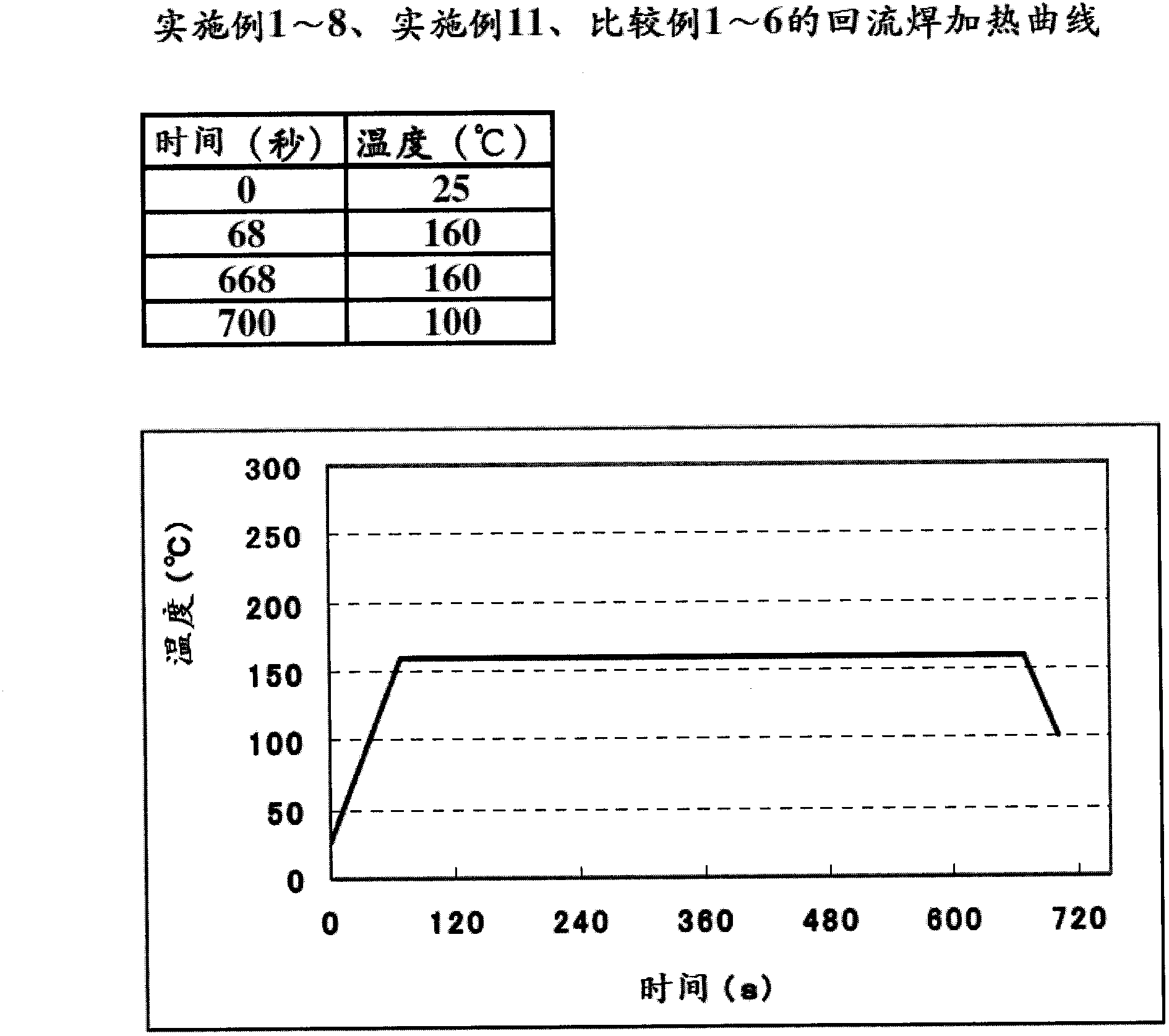
Embodiment 1~11、 comparative example 1~6
[0083] Hereinafter, an example in which the metal nanoparticle paste of the present invention is used as a conductive bonding material will be described.
[0084] (1) Compounding ingredients of metal nanoparticle paste
[0085] Conductive material
[0086] ·Metal nanoparticles covered by a protective film (hereinafter referred to as "coated metal nanoparticles")
[0087] Coated metal nanoparticles I: Tin nanoparticles are coated with a protective film composed of a sorbitan fatty acid ester of formula (I-1) by the above-mentioned active continuous interface vapor deposition method.
[0088] Coated metal nanoparticles II: Tin nanoparticles are coated with a protective film composed of oleylamine of formula (IV-1) by the above-mentioned active continuous interface vapor deposition method.
[0089] Coated metal nanoparticle III: The silver nanoparticle is coated with a protective film composed of the sorbitan fatty acid ester of the formula (I-1) by the active continuous interface vapor dep...
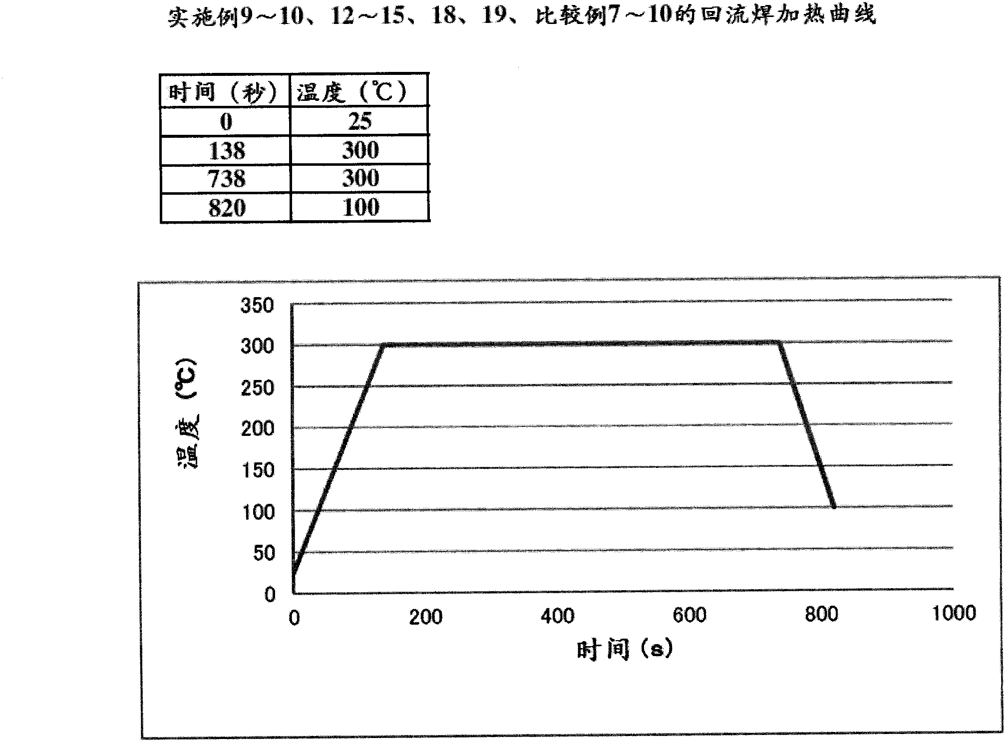
Embodiment 12~14、 comparative example 7
[0117] Hereinafter, an example in which the metal nanoparticle paste of the present invention is used as a wiring material will be described.
[0118] (1) Compounding ingredients of metal nanoparticle paste
[0119] Conductive material
[0120] The coated metal nanoparticle III and the coated metal nanoparticle IV are the same as the above-mentioned example in which the metal nanoparticle paste is used as the conductive bonding material.
[0121] The metal nanoparticle VI is a particle without a coating formed by a protective film.
[0122] (2) Preparation method of metal nanoparticle paste used as wiring material
[0123] A predetermined amount of the cyclohexane dispersion containing 20% by mass of coated metal nanoparticles obtained by the above-mentioned active continuous interface vapor deposition method was put into an agate mortar, and all the cyclohexane components were volatilized by vacuum drying to obtain a content of 20% by mass. % Protective film composition coated metal ...
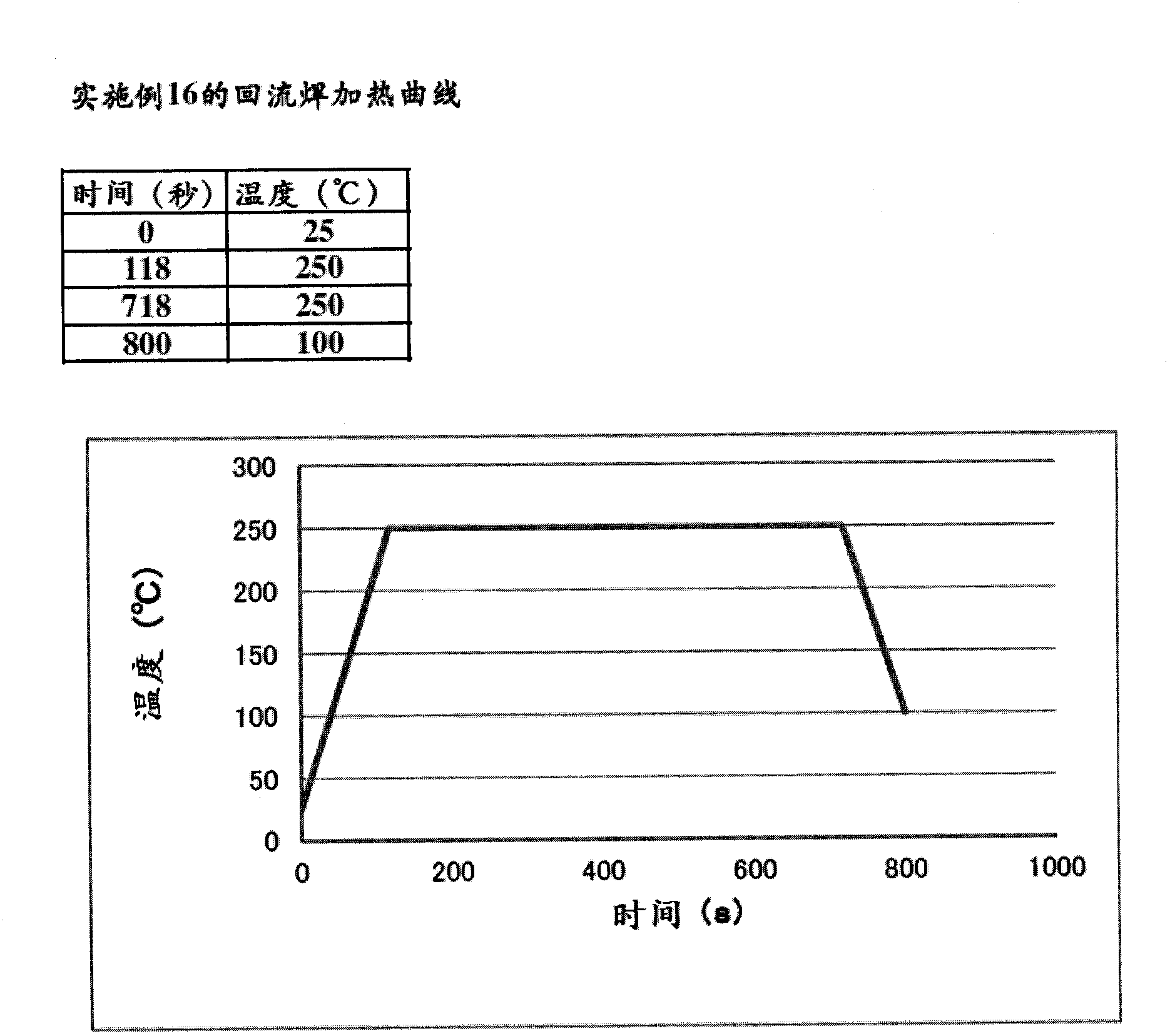
Embodiment 15~19、 comparative example 8~10
[0137] Hereinafter, an example in which the metal nanoparticle paste of the present invention is used as a coating film and bonding material having high reflectance will be described.
[0138] (1) Compounding ingredients of metal nanoparticle paste
[0139] Conductive material
[0140] -The coated metal nanoparticle III is the same as the coated metal nanoparticle III of the above-mentioned example in which the metal nanoparticle paste is used as the conductive bonding material.
[0141] ·The silver powder is "AgC-A" manufactured by Futian Metal Co., Ltd.
[0142] Dispersion medium
[0143] Terpineol C: a mixture of α-terpineol, β-terpineol, and γ-terpineol manufactured by Terpineol, Japan. The existing chemical substances are No. 3-2323, CAS. No. 8000-41-7, and the purity is over 85% by mass.
[0144] ·Dihydroterpineol: manufactured by Terpene Co., Ltd., 1-hydroxy-pair Alkane and 8-hydroxy-pair A mixture of alkanes. The existing chemical substances are No. 3-2315, CAS. No. 498-81-7, ...
PUM
| Property | Measurement | Unit |
|---|---|---|
| particle size | aaaaa | aaaaa |
| particle diameter | aaaaa | aaaaa |
| boiling point | aaaaa | aaaaa |
Abstract
Description
Claims
Application Information