Method for processing special-shaped hole through laser light
A technology of laser processing and special-shaped holes, which is applied in laser welding equipment, metal processing equipment, manufacturing tools, etc., can solve problems such as microcracks, low processing efficiency, and recrystallization, so as to improve service life and trouble-free running time, and improve The effect of thrust-to-weight ratio
- Summary
- Abstract
- Description
- Claims
- Application Information
AI Technical Summary
Problems solved by technology
Method used
Image
Examples
Embodiment 1
[0030] Two-dimensional oscillating optical micro-motion platform variable amplitude composite machining method
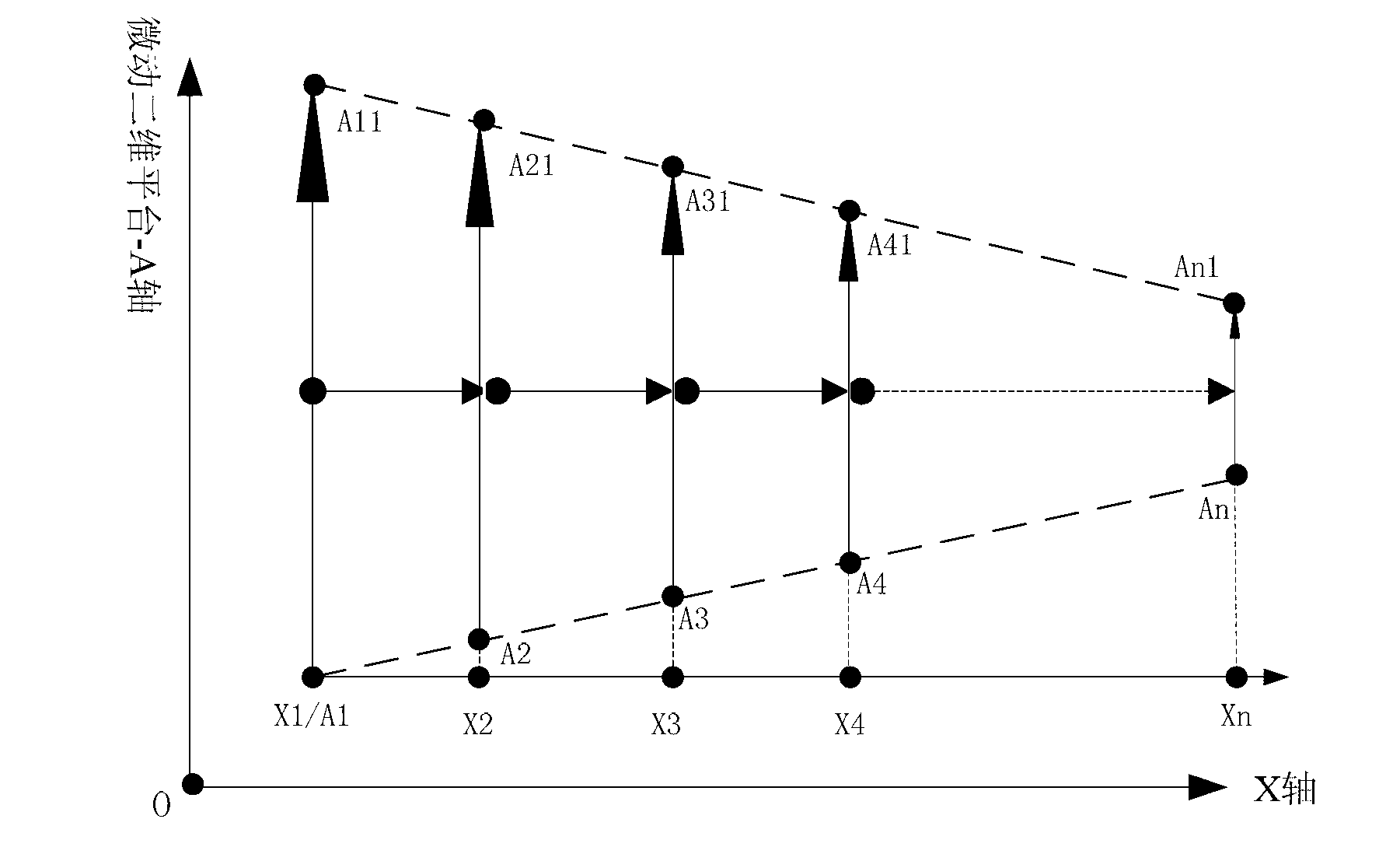
[0031] figure 2 As shown, the route trajectory of the laser scanning is the compound motion track of the A axis of the two-dimensional oscillating optical micro-motion platform 1 and the X-axis of the five-axis platform. It is the origin of the workpiece coordinate system.
[0032] The A-axis of the two-dimensional oscillating optical micro-motion platform 1 performs linear sweeping motion, and the X-axis of the five-axis platform pushes the workpiece forward. In order to process irregular chamfers on the surface of the workpiece, the scanning distance of the two-dimensional oscillating optical micro-motion platform 1 along the A axis, that is, its amplitude, changes with time. E.g, figure 2 Shown are: A1A11, A2A21, ..., AnAn1, as the X-axis of the five-axis platform advances the workpiece, a layer of trapezoidal bevel is formed on the surface of the workpiece....
Embodiment 2
[0036] Beam Shutter Variable Amplitude Composite Machining Method
[0037] Such as Figure 5 As shown, the line segments AnA1 and An1A11 are two contour lines of the special-shaped surface, and the line segments AnAn1 and A1A11 form the special-shaped surface. The two oblique lines are determined by the control timing of the beam shutter, that is, when the X-axis corresponds to the position of point X1, the beam shutter is opened at point A1 and closed at point A11, and corresponding to the position of point X2, the beam shutter is at point A2 Open at point A21, close at point A21, and so on. During this process, the micro-motion two-dimensional platform-A axis swings at a constant speed and equal amplitude.
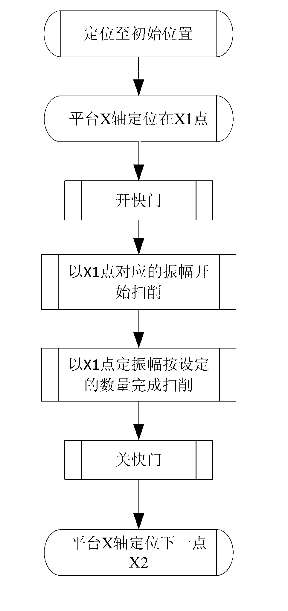
[0038] Such as Image 6 Shown is a control flow chart of a single-layer special-shaped surface passing through a beam shutter timing control method; Figure 7 It is the overall control flow chart of laser processing of special-shaped holes. The focus feed and X-axis...
PUM
 Abstract
Description
Claims
Application Information
 - R&D
- Intellectual Property
- Life Sciences
- Materials
- Tech Scout
- Unparalleled Data Quality
- Higher Quality Content
- 60% Fewer Hallucinations
Browse by: Latest US Patents, China's latest patents, Technical Efficacy Thesaurus, Application Domain, Technology Topic, Popular Technical Reports.
© 2025 PatSnap. All rights reserved.Legal|Privacy policy|Modern Slavery Act Transparency Statement|Sitemap|About US| Contact US: help@patsnap.com


