Automatic pipe bending and perforating integrated machine

An all-in-one machine and pipe technology, applied in the direction of boring/drilling, drilling/drilling equipment, other manufacturing equipment/tools, etc., can solve problems such as low production efficiency, easy to affect assembly, high error rate, etc., and achieve work quality And the effect of high production efficiency, reducing manual labor and meeting processing needs

Inactive Publication Date: 2013-04-03
ZHEJIANG YOTRIO GRP CO LTD
View PDF5 Cites 79 Cited by
  • Summary
  • Abstract
  • Description
  • Claims
  • Application Information

AI Technical Summary

Problems solved by technology

[0002] At present, with the development of the furniture industry, the scale of production is getting larger and larger. In order to improve production capacity and production efficiency, the demand for specialized production of various spare parts is also increasing, especially the pipes used as skeletons on furniture. It needs to be bent at various angles or holes for installation are opened on the pipe. If it is made by hand, the error rate is high and it is easy to affect the subsequent assembly. In order to improve this situation, people have designed automatic pipe benders and automatic punching machines. Hole machine, such as the Chinese patent (authorized announcement number: CN202070621U) discloses a pneumatic pipe bending machine, which includes a workbench, a cylinder and a cylinder assembly, a pipe bending groove, and a rolling groove. The cylinder piston of the cylinder passes through the telescopic shaft Connect the bend pipe groove, the bend pipe groove is provided with a semi-circular notch matching the diameter of the pipe, and the workbench is provided with two rolling grooves for positioning the two ends of the pipe and cooperating with the bend pipe groove to bend the pipe. There is a semicircular notch that matches the diameter of the pipe; the advance...

Method used


Image

  • Automatic pipe bending and perforating integrated machine
  • Automatic pipe bending and perforating integrated machine
  • Automatic pipe bending and perforating integrated machine

Examples


Embodiment Construction

[0035] The following are specific embodiments of the present invention and in conjunction with the accompanying drawings, the technical solutions of the present invention are further described, but the present invention is not limited to these embodiments.

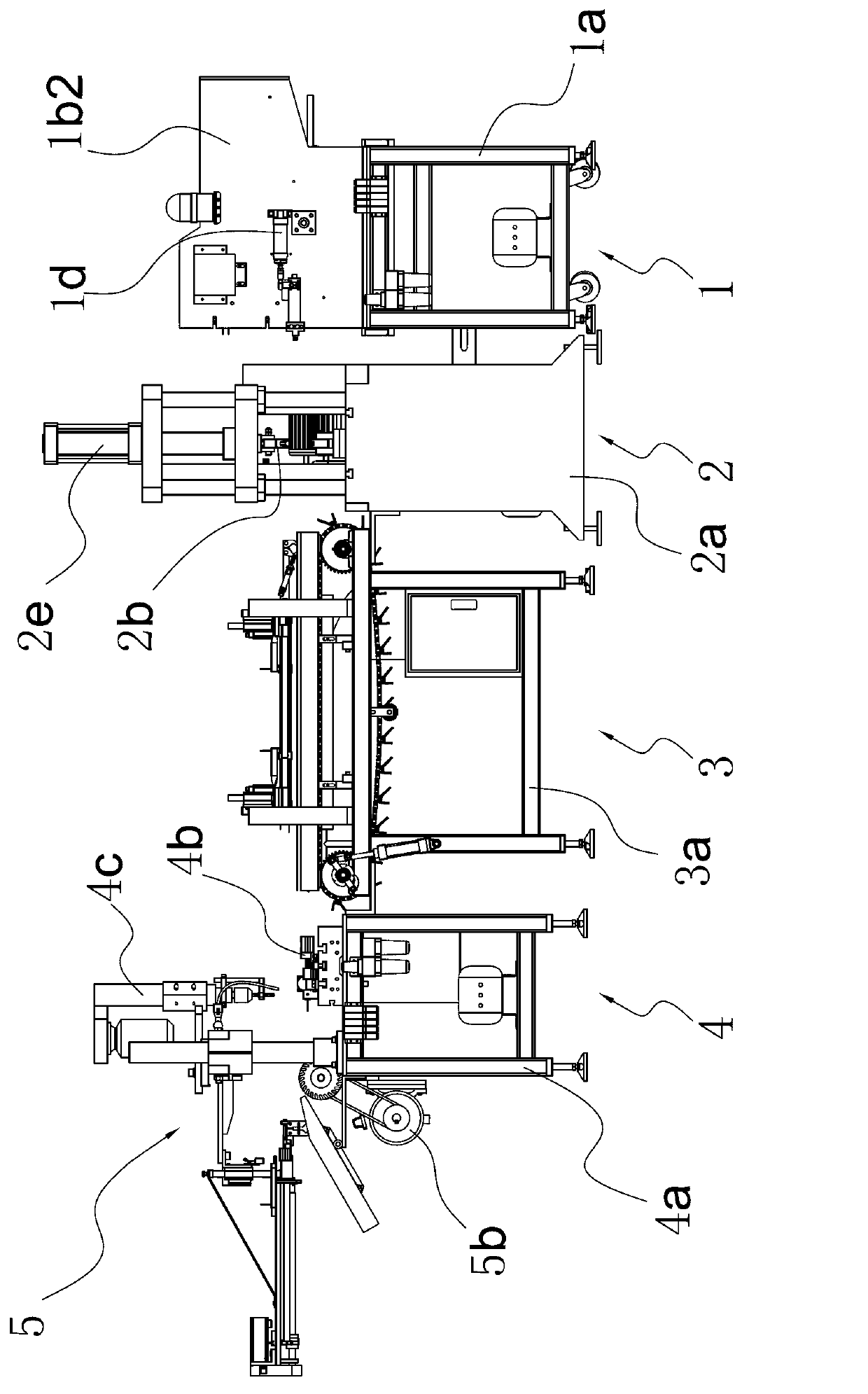
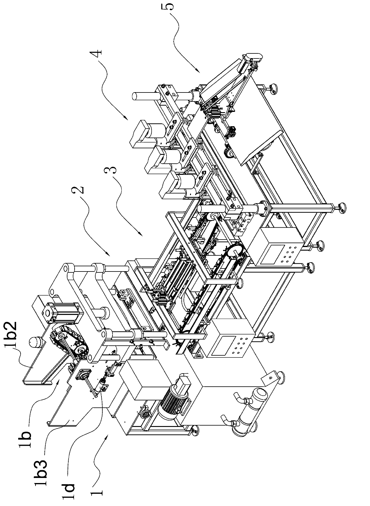
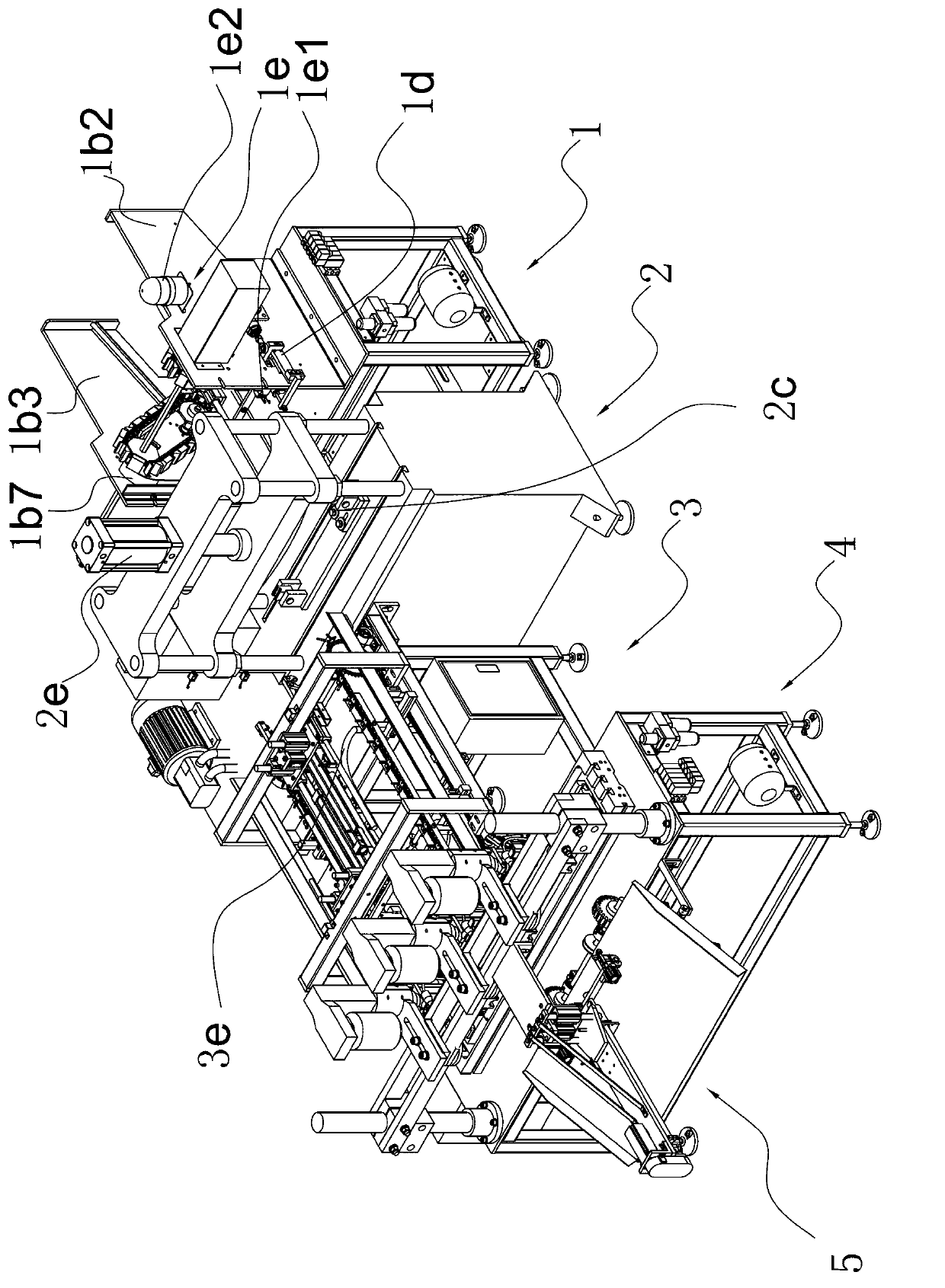
[0036] refer to figure 1 , figure 2 and image 3 , the present invention is an automatic pipe bending and punching integrated machine, including an automatic feeding mechanism 1 that provides a bending mechanism 2 for pipes, a delivery mechanism 3 that takes materials from the bending mechanism 2 and sends them to the punching mechanism 4, and completes the punching The final grinding unloading mechanism 5. Among them, the automatic feeding mechanism 1, the bending mechanism 2 and the conveying mechanism 3 have their own workbenches, which are respectively the feeding workbench 1a, the pipe bending workbench 2a and the conveying workbench 3a, the punching mechanism 4 and the grinding and unloading mechanism 5 Commonly ...


PUM


Abstract

The invention provides an automatic pipe bending and perforating integrated machine, and belongs to the technical field of machinery. The automatic pipe bending and perforating integrated machine solves problems of low production efficiency and poor consistency due to the fact that an existing pipe processing machine cannot realize automatic production. The automatic pipe bending and perforating integrated machine comprises a bending mechanism, a perforating mechanism, an automatic feeding mechanism, a conveying mechanism and a grinding and discharging mechanism, a die device is arranged on the bending mechanism, the conveying mechanism comprises a conveying worktable, a conveyer belt, a bending discharging manipulator, an adjusting device and a perforating feeding manipulator, and the adjusting device can adjust and position pipes placed on the conveyer belt. The automatic pipe bending and perforating integrated machine can automatically complete a series of working procedures such as feeding, bending, conveying, perforating, grinding and the like, and has the advantages of high automation degree and production efficiency and capability of saving production cost.

Description

technical field [0001] The invention belongs to the technical field of machinery, and relates to a pipe processing machine, in particular to a pipe automatic bending and punching integrated machine. Background technique [0002] At present, with the development of the furniture industry, the scale of production is getting larger and larger. In order to improve production capacity and production efficiency, the demand for specialized production of various spare parts is also increasing, especially the pipes used as skeletons on furniture. It needs to be bent at various angles or holes for installation are opened on the pipe. If it is made by hand, the error rate is high and it is easy to affect the subsequent assembly. In order to improve this situation, people have designed automatic pipe benders and automatic punching machines. Hole machine, such as the Chinese patent (authorized announcement number: CN202070621U) discloses a pneumatic pipe bending machine, which includes a...

Claims


Application Information

Patent Timeline
IPC IPC(8): B23P23/00B21D7/00B23Q7/00B23B41/00
Inventor 潘昌贵梁晓灵
Owner ZHEJIANG YOTRIO GRP CO LTD
Why Eureka
Try Eureka