Damping follow rest for turning slender axle

A slender shaft and tool holder technology, applied in turning equipment, tool holder accessories, large fixed members, etc., can solve the problems of tool chipping, affecting production efficiency and efficiency, tool wear, etc., to ensure the processing size and The effect of shape tolerance, improving product qualification rate and improving production efficiency

Active Publication Date: 2013-04-03
NUCLEAR POWER INSTITUTE OF CHINA +1
View PDF8 Cites 1 Cited by
  • Summary
  • Abstract
  • Description
  • Claims
  • Application Information

AI Technical Summary

Problems solved by technology

[0002] The processing of slender shafts has always been one of the difficulties in the machining industry. The main difficulty is that the rigidity of the workpiece is extremely poor, and it is easy to generate vibration under the action of cutting force, resulting in rough surface of the workpiece, and it is difficult to guarantee the tolerance of size and shape; followed by Aggravate tool wear, cause tool chipping, and even cause the possibility of scrapping the workpiece, seriously affecting production efficiency and benefits
[0003] At present, the commonly used method for processing slender shafts is to use a point-supported tool rest, which is an auxiliary device for radially supporting the rotating workpiece. During processing, it moves along the axial direction of the workpiece with the tool to reduce the cutting speed and feed rate. Using a smaller depth of cut and increasing the number of steady rests used to support the workpiece, but these common techniques cannot completely eliminate the vibration phenomenon during machining
[0004] After technical novelty checks, there is no better method and device that can effectively eliminate the vibration of the slender shaft during processing.

Method used


Image

  • Damping follow rest for turning slender axle
  • Damping follow rest for turning slender axle
  • Damping follow rest for turning slender axle

Examples


Embodiment

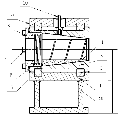
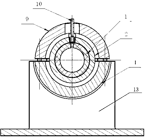
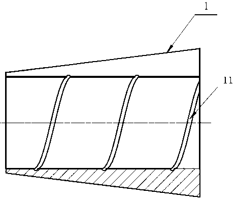
[0030] Such as Figures 1 to 4As shown, the present invention is a kind of vibration-damping tool rest for turning slender shafts. A support 13 is installed on the slide plate of the lathe, and a semi-cylindrical lower support 4 is installed on the support 13. The lower support 4 passes through the Bolts and connection methods are fixedly connected with an upper support 9, and the upper support 9 cooperates with the lower support 4 to form a cylindrical structure. Its interior is hollow, and a The fixed sleeve 2, the overall exterior of the fixed sleeve 2 is cylindrical, and two ring-shaped grooves parallel to each other are arranged on the inner side walls of the upper support 9 and the lower support 4, and an adjusting ring is installed in the groove 3. The adjustment ring 3 is two semi-annular structures, which match the groove and fit on the outer surface of the fixed sleeve 2. After the upper support 9 and the lower support 4 are connected by screws, the adjustment ring 3...


PUM


Abstract

The invention discloses a damping follow rest for turning a slender axle. The damping follow rest comprises a lower support seat and an upper support seat, wherein the upper support seat is matched with the lower support seat, the upper support seat and the lower support seat form a cylindrical hollow cavity structure, the inside of the hollow cavity is sheathed with a fixing sleeve, the inside of the fixing sleeve is provided with a damping sleeve which is provided with an inner hollow structure, the damping sleeve is in taper fit with the fixing sleeve, one larger-diameter end of the damping sleeve is provided with a spring, the spring is fixedly arranged in the fixing sleeve by an end cap, and the spring acts on the large-diameter end surface of the damping sleeve through a gasket. The damping follow rest has the advantages that the vibration is basically eliminated, so the influence caused by the abrasion of the damping sleeve is eliminated; the abrasion speed of an inner hole of the damping sleeve can be reduced by coolant, so a purpose of reducing the abrasion of the damping sleeve is realized; the use specifications of the support seats are reduced, and the material usage amount and the processing amount of the fixing sleeve are reduced, so a purpose of saving energy is realized; the processing size and the shape tolerance of a workpiece are ensured, and the qualified rate is improved; and the processing cost is effectively reduced, and the production efficiency is improved.

Description

technical field [0001] The invention relates to a machining tool, in particular to a vibration-damping tool rest for turning a slender shaft. Background technique [0002] The processing of slender shafts has always been one of the difficulties in the machining industry. The main difficulty is that the rigidity of the workpiece is extremely poor, and it is easy to generate vibration under the action of cutting force, resulting in rough surface of the workpiece, and it is difficult to guarantee the tolerance of size and shape; followed by Aggravate tool wear, cause tool chipping, and even cause the possibility of workpiece scrapping, seriously affecting production efficiency and benefits. [0003] At present, the commonly used method for processing slender shafts is to use a point-supported tool rest, which is an auxiliary device for radially supporting the rotating workpiece. During processing, it moves along the axial direction of the workpiece with the tool to reduce the c...

Claims


Application Information

Patent Timeline
IPC IPC(8): B23Q1/76B23B25/00
Inventor 胡运峰杨炯平
Owner NUCLEAR POWER INSTITUTE OF CHINA
Why Eureka
Try Eureka