
Rotary hearth furnace

A technology of rotary hearth furnace and furnace body, which is applied in the direction of furnace, hearth type furnace, furnace type, etc., and can solve the problems of low production efficiency of rotary hearth furnace process, uneven radiation heat transfer of material layer, low metallization rate, etc. Achieve the effect of improving heat transfer efficiency, improving heat transfer efficiency, and uniform heating

Inactive Publication Date: 2013-04-03
CHONGQING CISDI THERMAL & ENVIRONMENTAL ENG CO LTD
View PDF6 Cites 4 Cited by
  • Summary
  • Abstract
  • Description
  • Claims
  • Application Information

AI Technical Summary

Problems solved by technology

[0004] Since the rotary hearth furnace adopts the heating method of radiation heat transfer to reduce the iron oxides in the pellets / briquettes or briquettes by the carbon and volatile reducing gas in them, the high temperature heat of the burner combustion in the rotary hearth furnace depends on the flame Radiation heat transfer, because the material layer is still, the heat of the burning flame can only reach the surface of the material layer, and part of the heat can only reach the place 1~2 layers away from the surface through the gap of the material layer, so that the thickness of the material layer can only be 30 ~50mm, if the thickness of the material layer increases, the metallization rate and strength of the lower layer of pellets / briquettes are low, so the production efficiency of the rotary hearth furnace process is low
[0005] In view of this, in order to solve the defect that the material layer receives radiation and heat transfer unevenly due to the static material layer in the rotary hearth furnace, the present invention aims to explore a rotary hearth furnace that can increase the heat transfer of the material layer in the rotary hearth furnace Uniformity and heat transfer efficiency, and increased productivity of rotary hearth furnaces

Method used


Image

  • Rotary hearth furnace

Examples


Embodiment Construction

[0024] The specific implementation manners of the present invention will be described in detail below in conjunction with the accompanying drawings.

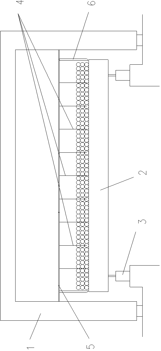
[0025] Such as figure 1 Shown is a schematic structural view of an embodiment of the rotary hearth furnace of the present invention. The rotary hearth furnace of this embodiment includes a furnace body 1 and at least one material layer stirring device fixedly arranged in the furnace body and above the rotating platform. The furnace body 1 is provided with a rotating platform 2 and is used to drive the rotating platform. 2. The driving mechanism for rotation. A supporting device 3 for supporting the rotating platform is provided under the rotating platform 2. The material layer stirring device includes at least one row of agitating rake teeth 4 extending toward the rotating platform 2 and used to stir the material layer placed on the rotating platform. . There are at least three material bed agitating devices in this embodiment...


PUM


Abstract

The invention discloses a rotary hearth furnace, which includes a furnace body, and at least one material layer stirring device fixedly arranged inside the furnace body and positioned above a rotating platform, wherein the rotating platform and a driving mechanism for driving the rotating platform to rotate are arranged inside the furnace body; a support device used for supporting the rotating platform is arranged under the rotating platform; the material layer stirring device includes at least one row of stirring rake teeth extending towards the rotating platform and used for stirring material layers placed on the rotating platform. According to the rotary hearth furnace provided by the invention, the material layer stirring device is arranged inside the furnace body, and the stirring rake teeth for stirring the material layers placed on the rotating platform are arranged on the material layer stirring device, so that during the operation of the rotary hearth furnace, the material layers are stirred by the stirring rake teeth to reserve new clearance among the material layers, as a result, radiating heat can be transferred to the lower material layer through the clearance, the lower material layer can be heated more completely and more uniformly, that is, the heat transfer efficiency for the radiating heat is improved, the thickness of the material layers can be increased, and the production efficiency of the rotary hearth furnace can be improved.

Description

technical field [0001] The invention relates to a rotary hearth furnace, in particular to a rotary hearth furnace capable of increasing the heat transfer efficiency of a material layer and making the material layer evenly heated. Background technique [0002] The rotary hearth furnace direct reduction process has the advantages of simple equipment, short production cycle and fast reaction speed, especially in the treatment of zinc-containing dust in iron and steel plants, which has great economic and social benefits. Therefore, the rotary hearth furnace process has been popular all over the world since its birth It has been widely promoted and become one of the mainstream processes of coal-based direct reduction process. [0003] The process of producing direct reduced iron by rotary hearth furnace process is as follows: evenly mix iron ore powder or zinc-containing dust with reducing agent (mainly coal powder) and then make pellets or briquettes, and dry carbon-containing p...

Claims


Application Information

Patent Timeline
IPC IPC(8): C21B13/10
Inventor 倪晓明郭秀键雍海泉程奇伯
Owner CHONGQING CISDI THERMAL & ENVIRONMENTAL ENG CO LTD
Learn More