
Air-inflated membrane structure with crossing cable net arranged along geodesic line

An inflatable membrane and geodesic technology, applied in special structures, building components, etc., can solve the problems of reducing the rigidity and bearing capacity of the inflatable membrane structure, affecting the distribution of internal force between the membrane surface and the cable, and increasing the difficulty of construction, so as to improve Effects of stability and economy, improvement of economy and safety, and simplification of construction difficulty

Inactive Publication Date: 2013-04-03
SHANGHAI JIAO TONG UNIV
View PDF11 Cites 8 Cited by
  • Summary
  • Abstract
  • Description
  • Claims
  • Application Information

AI Technical Summary

Problems solved by technology

The consequences of this are: when the inflatable membrane structure is formed, the cable and the membrane surface are not tightly fitted, and the cable has a large lateral swing under wind load, often leaving black scratches on the white membrane surface , affecting the aesthetics of the membrane structure
More importantly, the swing of the cable will affect the internal force distribution between the membrane surface and the cable, reducing the stiffness and bearing capacity of the inflatable membrane structure
At the same time, in order to limit the lateral movement of the cable, it is necessary to set up more nodes to connect the cables, which increases the difficulty of construction; and the force of the nodes is relatively large, and the nodes are often broken.

Method used


Image

  • Air-inflated membrane structure with crossing cable net arranged along geodesic line
  • Air-inflated membrane structure with crossing cable net arranged along geodesic line

Examples


Embodiment

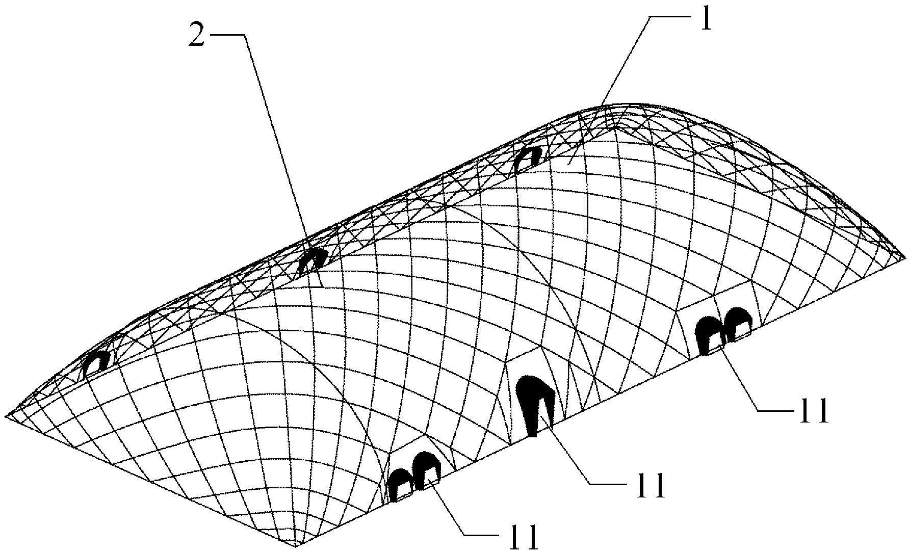
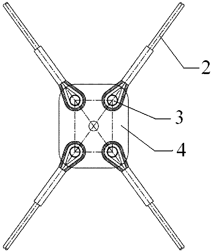
[0020] The cross-cable net inflatable membrane structure is arranged along the geodesic line, and its structure is as follows figure 1 As shown, the structure includes an inflatable membrane 1 and a cable 2 . Among them, the middle part of the inflatable film 1 is a cylinder after being inflated and formed, and the two ends are arc-shaped peripheral film surfaces with a smooth transition. The curvature of the peripheral film surface formed by the inflatable film 1 is a positive Gaussian curvature. Several entrances and exits 11 are arranged in the long side direction of the membrane surface, wherein the revolving door is the main entrance and exit, and the closed door is temporarily used as a safety door. The cable 2 starts from the anchor points at both ends and is arranged on the peripheral membrane surface along the geodesic direction, so that the lateral swing of the cable 2 can be minimized during normal use. The stay cables 2 forming a network structure are fixed on the...


PUM


Abstract

The invention relates to an air-inflated membrane structure with a crossing cable net arranged along a geodesic line. The air-inflated membrane structure comprises an air-inflated membrane and bracing cables, wherein after the air-inflated membrane is shaped through inflating, the middle part of the air-inflated membrane is of a cylindrical body, the two ends of the air-inflated membrane are of smooth-transition arc-shaped peripheral membrane faces, and the bracing cables are arranged on the peripheral membrane faces along the direction of the geodesic line in a manner that anchor points at the two ends of each bracing cable are taken as starting points. Compared with the prior art, the air-inflated membrane structure has the advantages that the concept that the geodesic line is the shortest in a spatial curved face is utilized, the crossing cable net is arranged at the periphery of the air-inflated membrane along the direction of the geodesic line, and the bracing cables are restricted to lateral movement and cannot be subjected to the problem of swinging under normal use; and as the bracing cables are restricted to the lateral movement, the number of nodes, connected with the bracing cables, in the whole peripheral crossing cable net can be accordingly reduced, the stress on the nodes is smaller, the difficulty of construction is reduced, and then, the economical efficiency and safety of the structure are increased.

Description

technical field [0001] The invention belongs to the technical field of building structures, and in particular relates to an inflatable membrane structure arranged with cable nets along a geodesic line, which is an innovation in the application of the inflatable cable-membrane structure. Background technique [0002] The inflatable membrane structure has the advantages of low cost, fast construction, easy installation and disassembly, large span, and good economic benefits. It is widely used in large-space, long-span sports and public facilities such as sports fields, exhibition halls, and warehouses. However, in practical engineering applications, the wind and snow resistance of the inflatable membrane structure is poor, so a certain number of cables are often arranged around the inflatable membrane in engineering to form a system in which the membrane surface and the cables bear external forces together. By controlling the internal force distribution on the membrane surface...

Claims


Application Information

Patent Timeline
IPC IPC(8): E04B1/34
Inventor 龚景海李中立冷予冰
Owner SHANGHAI JIAO TONG UNIV
Learn More