
Corrugated steel plate confined concrete combination column and manufacturing method thereof

A technology for confining concrete and corrugated steel plates, which is applied in the direction of columns, pier columns, pillars, etc., can solve the problems of poor confinement effect of core concrete, buckling of steel pipes, etc., and achieve superior mechanical properties, light weight, and good seismic performance

Inactive Publication Date: 2013-04-03
CHINA UNIV OF MINING & TECH
View PDF10 Cites 12 Cited by
  • Summary
  • Abstract
  • Description
  • Claims
  • Application Information

AI Technical Summary

Problems solved by technology

[0003] The purpose of the present invention is to overcome the problems that the traditional steel pipe processed by flat steel plates is prone to buckling and has poor confinement effect on the core concrete, and the corrugated steel plate has a strong circumferential restraint effect on the core concrete and the corrugated steel plate has a large out-of-plane rigidity, etc. Advantages of Proposed Concrete Composite Columns Confined by Corrugated Steel Plates

Method used


Image

  • Corrugated steel plate confined concrete combination column and manufacturing method thereof
  • Corrugated steel plate confined concrete combination column and manufacturing method thereof
  • Corrugated steel plate confined concrete combination column and manufacturing method thereof

Examples


Embodiment 1

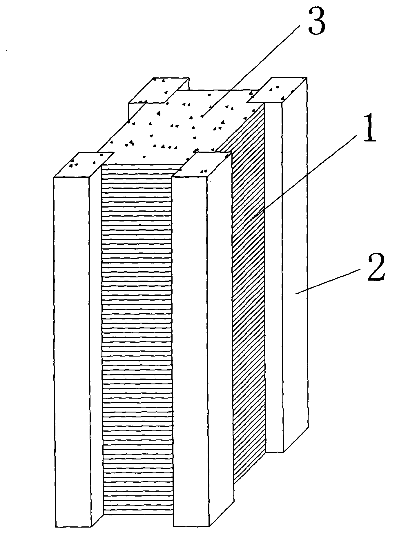
[0019] Such as figure 1 Shown is a corrugated steel plate confined concrete composite column. The composite column is formed by welding four corrugated steel plates 1 and four steel pipes 2 with a square cross section to form a quadrilateral pipe, wherein the four steel pipes 2 with a square cross section are located at the four vertices of the quadrilateral, and then between the quadrilateral pipe and the four square ( Or rectangular) steel pipe 2 is filled with concrete 3 and formed.

[0020] Its production method is as follows:

[0021] 1) Process corrugated steel plate 1 and square steel pipe 2 according to the designed size;

[0022] 2) A square steel pipe 2 is used as a corner and a corrugated steel plate 1 is welded to form a quadrilateral pipe, and the corrugated direction of the corrugated steel plate 1 is the same as the length direction of the quadrilateral pipe;

[0023] 3) Fill the concrete 3 in the quadrilateral pipe and the corner square steel pipe 1 .

Embodiment 2

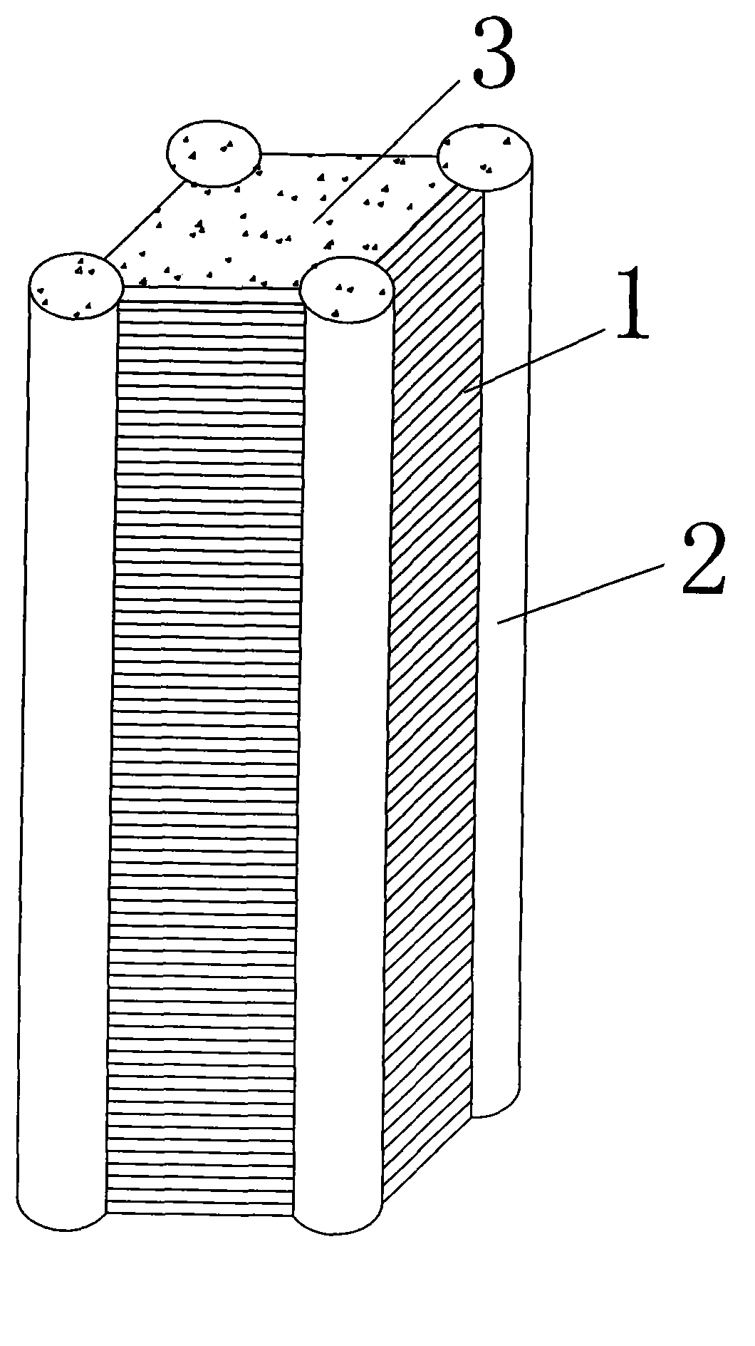
[0025] Such as figure 2 Shown is another corrugated steel plate confined concrete composite column. The composite column is formed by welding four corrugated steel plates 1 and four circular steel pipes 2 to form a quadrilateral pipe, wherein the four circular steel pipes 2 are located at the four vertices (i.e. corners) of the quadrilateral, and then the quadrilateral pipe and the four The circular steel pipe 2 is filled with concrete 3 and formed. Its production method is as follows:

[0026] 1) Process the corrugated steel plate 1 and the circular steel pipe 2 according to the designed size;

[0027] 2) The circular steel pipe 2 is used as the corner and the corrugated steel plate 1 is welded to form a quadrilateral pipe, and the corrugated direction of the corrugated steel plate 1 is the same as the length direction of the quadrilateral pipe;

[0028] 3) Concrete 3 is filled in the square pipe and the round steel pipe 1 at the corner.

Embodiment 3

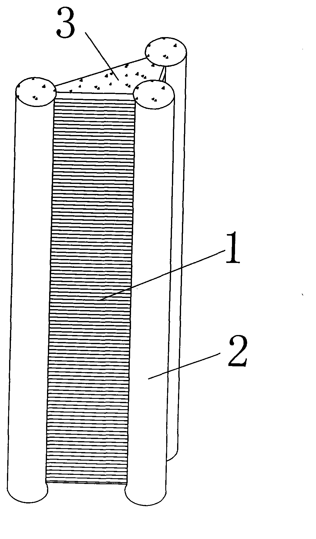
[0030] Such as image 3 Shown is another corrugated steel plate confined concrete composite column. The composite column is composed of three corrugated steel plates 1 and three circular steel pipes 2 welded to form a triangular pipe, wherein the three circular steel pipes 2 are located at the three vertices of the triangle, and then the triangular pipe and the Three circular steel pipes 2 are filled with concrete 3 to form. Its production method is as follows:

[0031] 4) Process the corrugated steel plate 1 and the circular steel pipe 2 according to the designed size;

[0032] 5) The round steel pipe 2 is used as the corner and the corrugated steel plate 1 is welded to form a triangular pipe, and the corrugated steel plate 1 has the same corrugated direction as the length direction of the triangular pipe;

[0033] 6) Concrete 3 is filled in the triangular pipe and the round steel pipe 1 at the corner.


PUM


Abstract

The invention discloses a corrugated steel plate confined concrete combination column which is a polygon tube formed by using a plurality of corrugated steel plates and a plurality of steel tubes as turning corners, wherein the corrugation directions of the corrugated steel plates are identical to the length direction of the polygon tube; and concrete is further filled into the polygon tube and the corners so as to manufacture the combination column. In addition to the excellent mechanical property of the conventional steel tube concrete, the combination column further has the following remarkable advantages that the load born by corrugated steel plate bears in the corrugation direction is small, so that the strength of the corrugated steel plate is mainly for providing annular restraint on the core concrete, then the compression bearing capacity of the core concrete is greatly improved, the compression bearing capacity of the combination column is improved to a large extent, the material is saved, and the engineering cost is reduced; the outer rigidity of the plane of the corrugated steel plate is large, and the corrugated steel plate is unlikely to bulge under the transverse expansion deformation action of the core concrete, so that the effective annual restraint of the corrugated steel plate to the core concrete is increased, and the compression bearing capacity of the combination column is further improved.

Description

technical field [0001] The invention relates to a form of building components, in particular to a corrugated steel plate confined concrete composite column applied in the field of civil engineering and a manufacturing method thereof. Background technique [0002] Confined steel tube concrete columns, that is, concrete-filled steel tube columns, refer to composite structural members formed by filling concrete in steel tube cavities. The basic principles are as follows: 1) The core concrete is in a three-dimensional compression state by using the confinement effect of the steel pipe on the concrete filled inside the steel pipe, so that the core concrete has a higher compressive strength and compression deformation capacity; 2) With the help of the internal concrete The supporting function of the steel pipe can enhance the geometric stability of the steel pipe wall and change the instability mode of the hollow steel pipe, thereby improving the compressive bearing capacity of th...

Claims


Application Information

Patent Timeline
Patent Type & Authority Applications(China)
IPC IPC(8): E04C3/34
Inventor 李贤夏俊夏承柱梁彦烁赵泽华
Owner CHINA UNIV OF MINING & TECH
Learn More