Method for repairing heat recovery steam generator tube-to-header damage

a heat recovery steam generator and head-to-header technology, which is applied in the direction of electrical wiring devices, lighting and heating apparatus, soldering apparatus, etc., can solve the problems of thermal fatigue failure at the toe of the tube weld, life limiting factors of many heat recovery steam generators, and difficulty in repairing heat exchanger tubes and head-to-header damage, etc., to reduce the number of welds and the time required

Inactive Publication Date: 2009-09-10
ELECTRIC POWER RES INST INC
View PDF25 Cites 7 Cited by
  • Summary
  • Abstract
  • Description
  • Claims
  • Application Information

AI Technical Summary

Benefits of technology

[0007]Repairing HRSG header-to-tube damage from inside the header (as opposed to the outside) significantly reduces the opportunity for subsequent failures to repaired tubes and provides a more fatigue-resistant attachment design to those currently found in the industry. The method provided reduces the number of welds required as well as the time required to complete the repair.

Problems solved by technology

One of the life limiting factors for many heat recovery steam generators (HRSGs) is associated with damage that occurs at header-to-tube attachments.
This attachment is particularly troublesome due to thermal differences experienced between the header and the tubes during cyclic operation.
Thermal shock results and often leads to thermal fatigue failures at the toe of the tube weld.
This results in restricted thermal expansion.
Anomalies in temperature and flow rate of the fluid between tubes in the same row can cause significant differences in the average temperatures of the set of tubes attached to the same headers.
During start-ups and shutdowns, these transient conditions place abnormal stresses on the tubes and tube attachments, eventually resulting in damage to the attachments.
This approach (commonly referred to as “cutting your way in and welding your way out”) is time consuming, costly, and more often than not, results in poor weld quality due to limited accessibility.

Method used


Image

  • Method for repairing heat recovery steam generator tube-to-header damage
  • Method for repairing heat recovery steam generator tube-to-header damage
  • Method for repairing heat recovery steam generator tube-to-header damage

Examples


Embodiment Construction

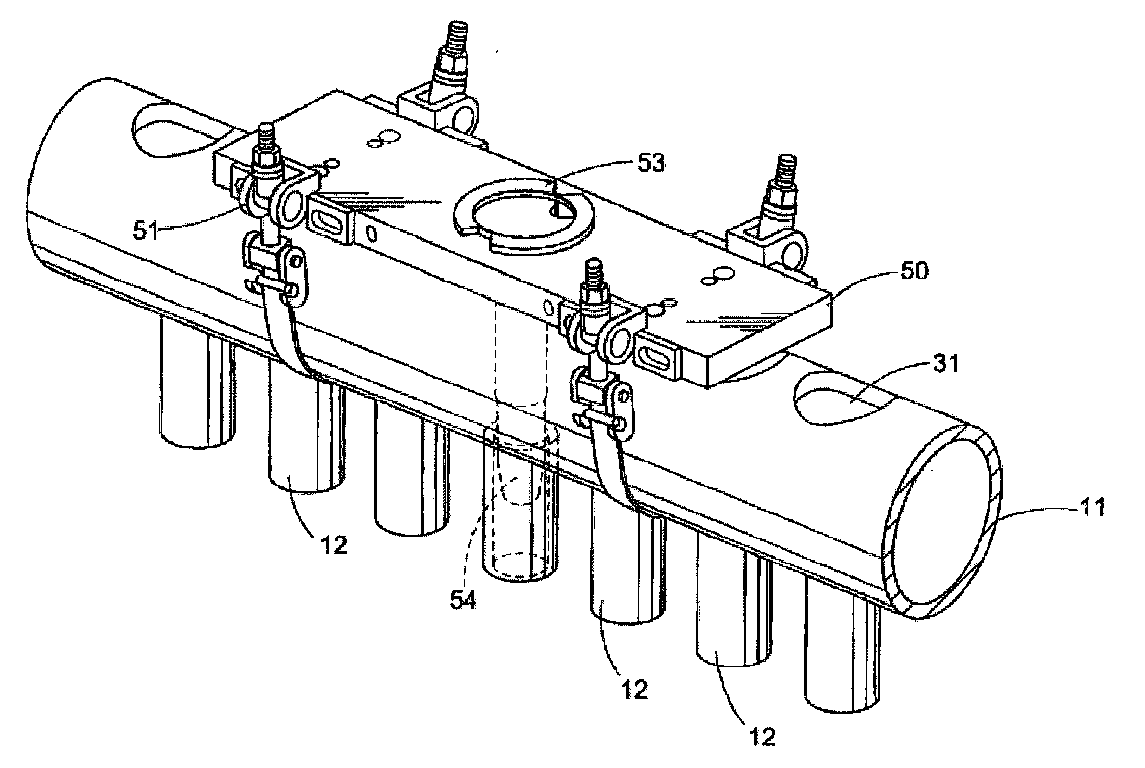
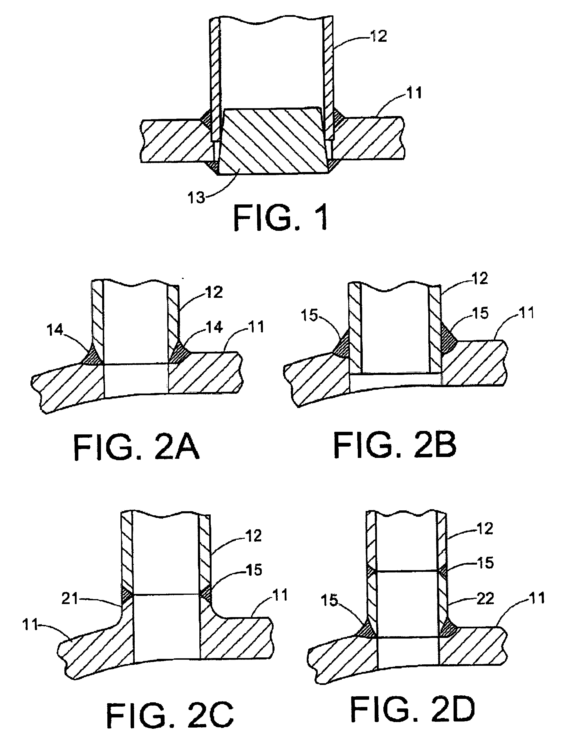
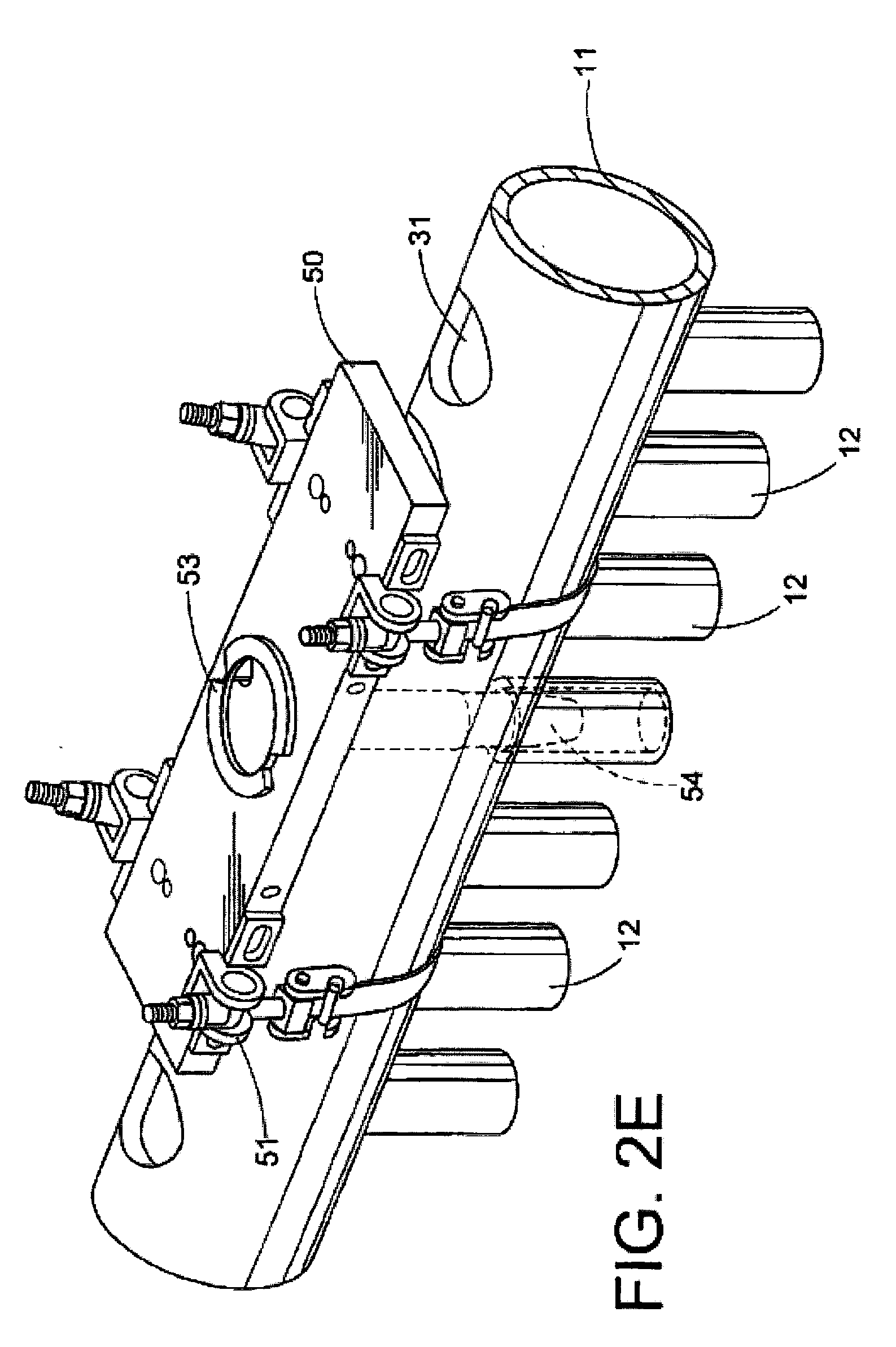
[0031]The present method provides a more pragmatic approach to address HRSG header-to-tube attachment damage than is currently used by industry today. This form of repair is often more difficult than conventional tube repairs due to limited access to the damage location. As a result, tube and header to tube attachment failures are often left in place and simply plugged. FIG. I illustrates a plug weld configuration. Plugging requires removal of an access window within the header 11 one hundred eighty (180) degrees away from the stub tube 12 attachment location, machining and insertion of a plug 13 into the damaged tube bore, welding of the plug into place, and then re-installation of the window.

[0032]Repair methodology is complicated by the number of different attachment configurations used by industry. Header to tube attachment weld designs used by original equipment manufacturers (OEMs) include:

[0033]a) partial penetration welds 14 (shown in FIG. 2A);

[0034]b) fall penetration welds...


PUM

PropertyMeasurementUnit
diameteraaaaaaaaaa
outer diameteraaaaaaaaaa
diameteraaaaaaaaaa

Abstract

A method for repairing a heat recovery steam generator (HSRG) header to tube attachment damage, includes providing an access window in the header opposite the damaged header to tube attachment location; removing the header to tube attachment damage; inserting a tapered stub tube into a header penetration centered axially immediately over the tube; effecting a profile weld between the header and the tapered stub tube at the header penetration from the inside surface of the header; welding the tapered stub tube to the existing tube through the header inside diameter; welding shut the access window; and completing a post weld heat treatment of all the welds.

Description

CROSS REFERENCE TO RELATED APPLICATIONS[0001]This application is a continuation of U.S. Ser. No. 11 / 364,604, filed on Feb. 28, 2006, which claims the benefit of the filing date of U.S. Provisional Application for Patent Ser. No. 60 / 656,959 filed Feb. 28, 2005, both of which are incorporated herein by reference.FIELD OF INVENTION[0002]The present invention is directed to a method for repairing heat exchanger tube and tube attachment damage, such as for heat transfer applications. More specifically, the disclosed method is related to a method for repairing a heat recovery steam generator (HSRG) tube damage and tube to header attachment damage, for applications such as electricity producing power plants, such as fossil fuel plants.BACKGROUND[0003]One of the life limiting factors for many heat recovery steam generators (HRSGs) is associated with damage that occurs at header-to-tube attachments. This attachment is particularly troublesome due to thermal differences experienced between th...

Claims


Application Information

Patent Timeline
Patent Type & Authority Applications(United States)
IPC IPC(8): B23P6/00
CPCB23K1/0012Y10T29/49352B23K9/0288B23K9/16B23K26/28B23K37/053B23K2201/06B23K2201/14B23P6/00F16L55/179F22B37/003F22B37/104F28F9/182F28F11/00Y10T29/49728B23K9/0286B23K2101/06B23K2101/14
Inventor GANDY, DAVID WAYNEFREDERICK, GREGCOLEMAN, KENT
Owner ELECTRIC POWER RES INST INC
Why Eureka
Try Eureka