Efficient energy-saving device for fuel engine

A high-efficiency and energy-saving technology for fuel engines, applied in combustion engines, internal combustion piston engines, engine components, etc., can solve the problems of uneven flashover of each cylinder, insufficient endurance, fuel waste, etc., to achieve strong explosion power, less oil consumption, high ignition effect

Inactive Publication Date: 2013-04-03
肖信君
View PDF3 Cites 1 Cited by
  • Summary
  • Abstract
  • Description
  • Claims
  • Application Information

AI Technical Summary

Problems solved by technology

[0002] At present, in the field of fuel engines, there are engines such as direct fuel injection, spark ignition, and electronic injection. These engines have the following disadvantages: one is that the fuel injection nozzle of the direct injection engine drips oil and the atomization is poor; There are problems in the rear line, etc., resulting in uneven flashover of each cylinder and incomplete fuel combustion; third, black smoke appears in the exhaust pipe when the engine is accelerated by heavy loads during work, resulting in insufficient engine power and endurance; When starting at low temperature, the engine fuel is incompletely burned, and white smoke and blue smoke appear at the exhaust pipe; fifth, there is water dripping out of the exhaust pipe; sixth, there is too much carbon deposit in the piston ring groove of the engine and the valves of each cylinder; The noise of the engine is too loud; the eighth reason is that the intake air is not enough when the engine is under heavy load and high-speed operation, resulting in insufficient horsepower
The main reason for the above shortcomings is that part of the fuel in the mixture in the piston cylinder is discharged out of the piston cylinder without sufficient combustion, polluting the air and causing fuel waste.

Method used


Image

  • Efficient energy-saving device for fuel engine

Examples


Embodiment Construction

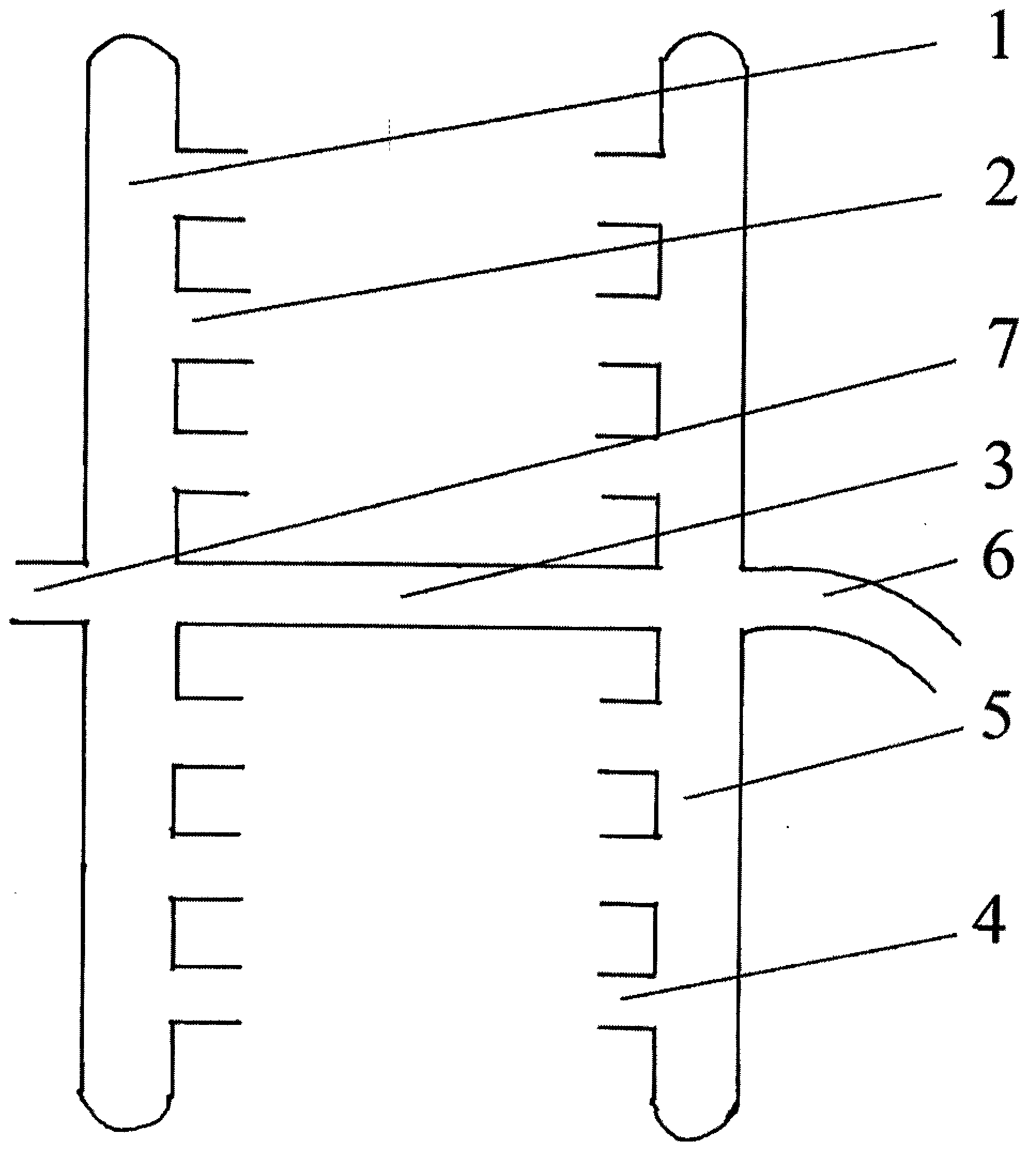
[0008] Referring to the accompanying drawings, a hole is respectively opened in the corresponding place between the total intake pipe 1 and the total exhaust pipe 5 of the six-cylinder fuel engine between the third cylinder and the fourth cylinder, and the connecting pipe 3 is used to connect these two holes, which makes the cost Invented high-efficiency energy-saving device for fuel engines.

[0009] When the fuel engine is working, the air enters the intake inlet 2 of each cylinder from the total intake port 7 through the total intake pipe 1, and then is discharged from the exhaust outlet 4 of each cylinder to the total exhaust pipe 5, and then enters the total intake through the connecting pipe 3. The air pipe 1 reciprocates in this way, so that the main intake pipe 1 absorbs a large amount of high-temperature and high-heat gas discharged from the main exhaust pipe into each piston cylinder, and becomes a high-quality fuel with a high ignition point, less oil consumption, st...


PUM


Abstract

The invention relates to an efficient energy-saving device for a fuel engine. The device is characterized in that a hole is respectively formed in each of the middle parts of a total air inlet tube (1) and a total air outlet tube (5) of the fuel engine. The two holes are connected by a pipeline (3), so that the total air inlet tube (1) is communicated with the total air outlet tube (5). According to the efficient energy-saving device for the fuel engine provided by the invention, a high-temperature high-calorific exhaust pipeline of the engine is communicated with the air inlet pipe, so that after the engine is started, high-temperature high-calorific good gases exhausted by the air outlet pipe during air absorption enter into piston cylinders and become high-quality fuel mixed gases which are high in combustion point, less in oil consumption and strong in brisance, and can be adequately combusted. The deficiency of an original fuel engine is solved, so that fuel which is not adequately combusted combusts adequately, and the efficient and energy-saving purposes are realized.

Description

1. Technical field [0001] The invention relates to an energy-saving device, in particular to a high-efficiency energy-saving device for a fuel engine. 2. Background technology [0002] At present, in the field of fuel engines, there are engines such as direct fuel injection, spark ignition, and electronic injection. These engines have the following disadvantages: one is that the fuel injection nozzle of the direct injection engine drips oil and the atomization is poor; There are problems in the rear line, etc., resulting in uneven flashover of each cylinder and incomplete fuel combustion; third, black smoke appears in the exhaust pipe when the engine is accelerated by heavy loads during work, resulting in insufficient engine power and endurance; When starting at low temperature, the engine fuel is incompletely burned, and white smoke and blue smoke appear at the exhaust pipe; fifth, there is water dripping out of the exhaust pipe; sixth, there is too much carbon deposit in t...

Claims


Application Information

Patent Timeline
Patent Type & Authority Applications(China)
IPC IPC(8): F02M25/07F02M26/01
CPCY02T10/121Y02T10/12
Inventor 肖信君
Owner 肖信君
Why Eureka
Try Eureka