Wheel hub motor and control method thereof

A technology of hub motor and control method, which is applied in the direction of electronic commutation motor control, control system, synchronous motor with stationary armature and rotating magnet, etc., which can solve the problems of increasing processing difficulty, weak anti-interference ability, and installation of position detection device Limited space and other issues, to save cost and installation space, strong impact and oil pollution resistance, and improve rapid response

Inactive Publication Date: 2013-04-03
ZHEJIANG ZHONGKE DERUN TECH
View PDF12 Cites 10 Cited by
  • Summary
  • Abstract
  • Description
  • Claims
  • Application Information

AI Technical Summary

Problems solved by technology

However, the magnetoelectric position detection device has the following disadvantages in physical structure: the inner side of the stator is generally arc-shaped and smooth, the sensor is not easy to install and fix, and it is easy to cause positioning errors, which in turn causes the phase deviation of the signal, making the high-order harmonics in the signal The weight is large; the manufacturing process is complicated, which is not conducive to industrialization; the reliability is low, the sensors are evenly distributed on the inner wall, and the supporting substrate of the sensor must be a flexible body, such as: FPC, etc., but its tensile strength is not high, easy to break, and increases It increases the difficulty of processing and affects the life of the product; at the same time, the magnetic field induced by the sensor leaks a lot, and the magnetic field cannot be fully applied, which makes the noise in the signal large and affects the measurement accuracy; the overall structure of the product requires the sensor to be small, which makes the product cost relatively high
In this process, what the position sensor detects is not the absolute mechanical position of the motor rotor; and the output control signal is a square wave, which cannot realize pure sinusoidal current

Method used


Image

  • Wheel hub motor and control method thereof
  • Wheel hub motor and control method thereof
  • Wheel hub motor and control method thereof

Examples


Example Embodiment

[0063] Example one

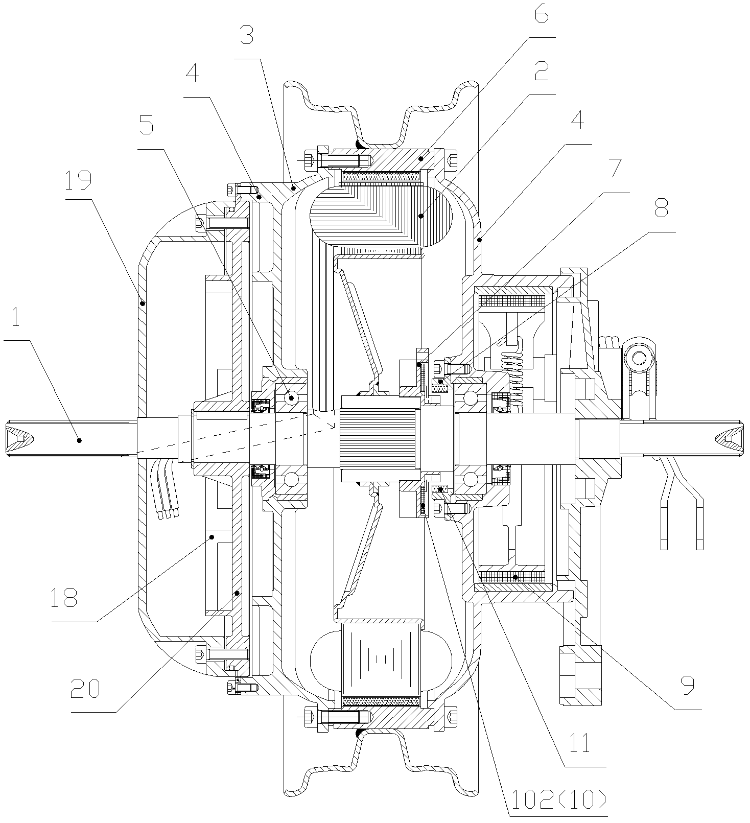
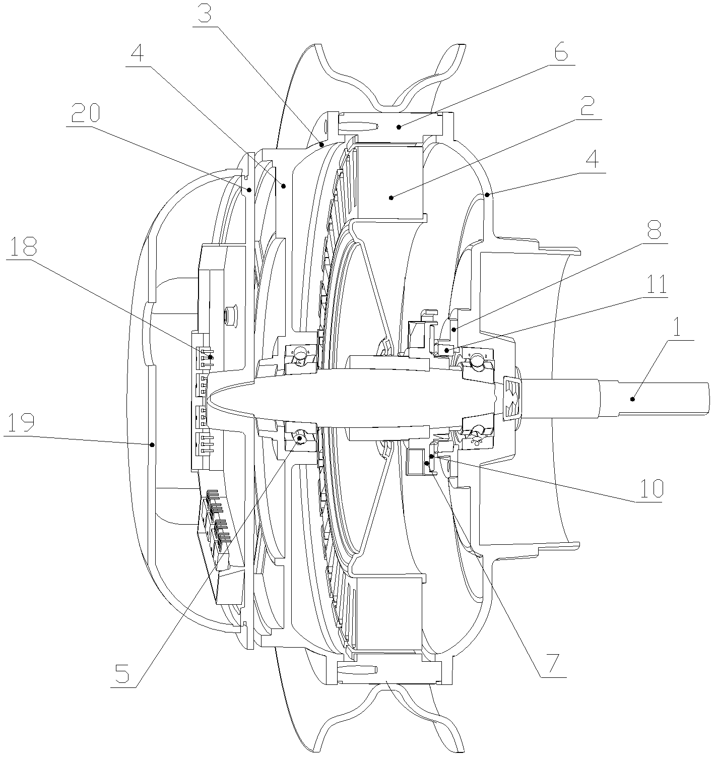
[0064] figure 1 It is a schematic diagram of the overall structure of an in-wheel motor with an external opposite side according to the first embodiment of the present invention, figure 2 It is a schematic diagram of the three-dimensional structure of a hub motor with an external opposite side according to an embodiment of the present invention. Such as figure 1 And combine figure 2 As shown, the present invention provides a hub motor, including a motor shaft 1 and a stator 2 fixed thereon. The stator 2 is sheathed with a rotor housing 3, and the front and rear ends of the rotor housing 3 pass through a rotor end cover 4 and a bearing, respectively. 5 is rotatably fixed on the motor shaft 1, the outer side of the rotor end cover 4 at the rear end is connected with the hub brake assembly 9, and the rotor housing 3 is connected with the hub 6. The corresponding position of the in-wheel motor is provided with a position detection device. The position detection...

Example Embodiment

[0074] Example two

[0075] Figure 5 It is a cross-sectional view of the overall structure of the external hub motor on the same side of the second embodiment of the present invention; Image 6 It is a schematic diagram of the three-dimensional structure of an external hub motor on the same side in the second embodiment of the present invention. Such as Figure 5 And combine Image 6 As shown, in this embodiment, the position detection device and the servo controller 18 are arranged on the same side of the stator 2, and the servo controller 18 is fixed on the opposite side of the stator 2 where the hub brake assembly 9 is installed. The mounting holes on the PCB board of the servo controller 18 and the threaded holes on the chassis 20 are fixed by screws; the magnetic steel ring 11 in the position detection device is inside the motor rotor end cover 4 on the opposite side of the mounting hub brake assembly 9 The stepped part is clearance fit and fixed; the Hall PCB board 102 wit...

Example Embodiment

[0118] Example three

[0119] Picture 12 It is a schematic diagram of the overall structure of the built-in hub motor in the third embodiment of the present invention; Figure 13 This is the assembly diagram of the built-in hub motor in the third embodiment of the present invention. Such as Picture 12 And combine Figure 13 As shown, in the hub motor of this embodiment, the servo controller 18 is arranged in the inner cavity of the motor, and the servo controller 18 is equipped with a hub brake through the mounting hole on the servo controller PCB board and the stator bracket 22 The threaded holes on the opposite side of the assembly 9 are positioned and locked on the stator support 22 by screws. The outer cover is provided with a rotor end cover 4.

[0120] Such as Picture 12 And combine figure 1 , Figure 5 As shown, the built-in structure of the controller in this embodiment is compared with the external structure in the first and second embodiments. The servo controller 18 i...


PUM


Abstract

The invention relates to a wheel hub motor and a control method thereof. The wheel hub motor comprises a motor shaft (1) and a stator (2), wherein a rotor shell (3) is sleeved outside the stator (2), and the front end and the back end of the stator (2) are rotatablely fixed on the motor shaft (1) through a rotor end cover (4) and a bearing (5); the outer side of the rotor end cover (4) is connected with a hub brake component (9); the rotor shell (3) is connected with a wheel hub (6); a position detection device is arranged at a position corresponding to the wheel hub motor, and comprises a retainer (7) which is fixed on the motor shaft (1) and a magnetic steel ring (11) which is fixed on the rotor end cover (4); a plurality of Hall elements (10) are arranged on the retainer (7); a servo controller (18) is arranged on the motor shaft (1); and the rotor end cover 94) and the motor shaft (1) rotate relatively. The wheel hub motor is simple in structure, energy-saving, high in starting characteristic, small in size, and high in efficiency.

Description

technical field [0001] The invention relates to a hub motor and a control method thereof, in particular to a hub motor with a position detection device applied to an electric bicycle and a control method thereof. Background technique [0002] With the development of the economy and the improvement of people's living standards, electric vehicles such as electric mopeds, electric bicycles, electric motorcycles, small electric cars, electric cars, and electric buses are gradually emerging in urban traffic. As a new generation of electric vehicles, electric wheel vehicles need to improve the hub motor, a key component, in order to improve performance and reduce costs. [0003] The operating characteristic of the drive motor for vehicles is that the motor is powered by the battery, and strives to enable the limited energy to travel the longest mileage, which is closely related to the performance of the drive motor. Therefore, the starting torque of the motor, the overload capaci...

Claims


Application Information

Patent Timeline
IPC IPC(8): H02K21/24H02K11/00H02P6/00H02K11/215
Inventor 郝双晖吴海苗蔡一
Owner ZHEJIANG ZHONGKE DERUN TECH
Why Eureka
Try Eureka