Switched reluctance motor of cast-aluminum rotor structure

A technology of switched reluctance motors and cast aluminum rotors, applied in the direction of magnetic circuit shape/style/structure, electric components, electrical components, etc., can solve the problems of low motor power density, large noise and vibration, low power factor, etc., to achieve Improve power output density and effective material utilization, reduce vibration and noise, reduce weight and cost

Active Publication Date: 2015-07-15
GUODIAN UNITED POWER TECH
View PDF4 Cites 0 Cited by
  • Summary
  • Abstract
  • Description
  • Claims
  • Application Information

AI Technical Summary

Problems solved by technology

[0005] However, the traditional switched reluctance motor has large noise and vibration and strong nonlinearity during operation; the motor has a double salient pole structure, and its stator and rotor are laminated by ordinary silicon steel sheets; there is neither winding nor permanent magnet on the rotor. Concentrated windings are wound on the stator tooth poles. Therefore, there are still disadvantages such as low power density of the motor, low effective utilization of materials, low power factor, heavy weight and high cost of the motor, which to a certain extent affect its special use in the field of speed regulation. It is the application promotion in the field of direct drive wind power generation
[0006] It can be seen that the traditional switched reluctance motor still has obvious defects and deficiencies in structure and use, and needs to be further improved. How to create a new type of switched reluctance motor to improve power density, effective material utilization, and Power factor, and reduce the weight, cost, vibration and noise of the motor, making it more suitable for direct drive wind power generation, which is one of the current important research and development fields

Method used


Image

  • Switched reluctance motor of cast-aluminum rotor structure
  • Switched reluctance motor of cast-aluminum rotor structure
  • Switched reluctance motor of cast-aluminum rotor structure

Examples


Embodiment Construction

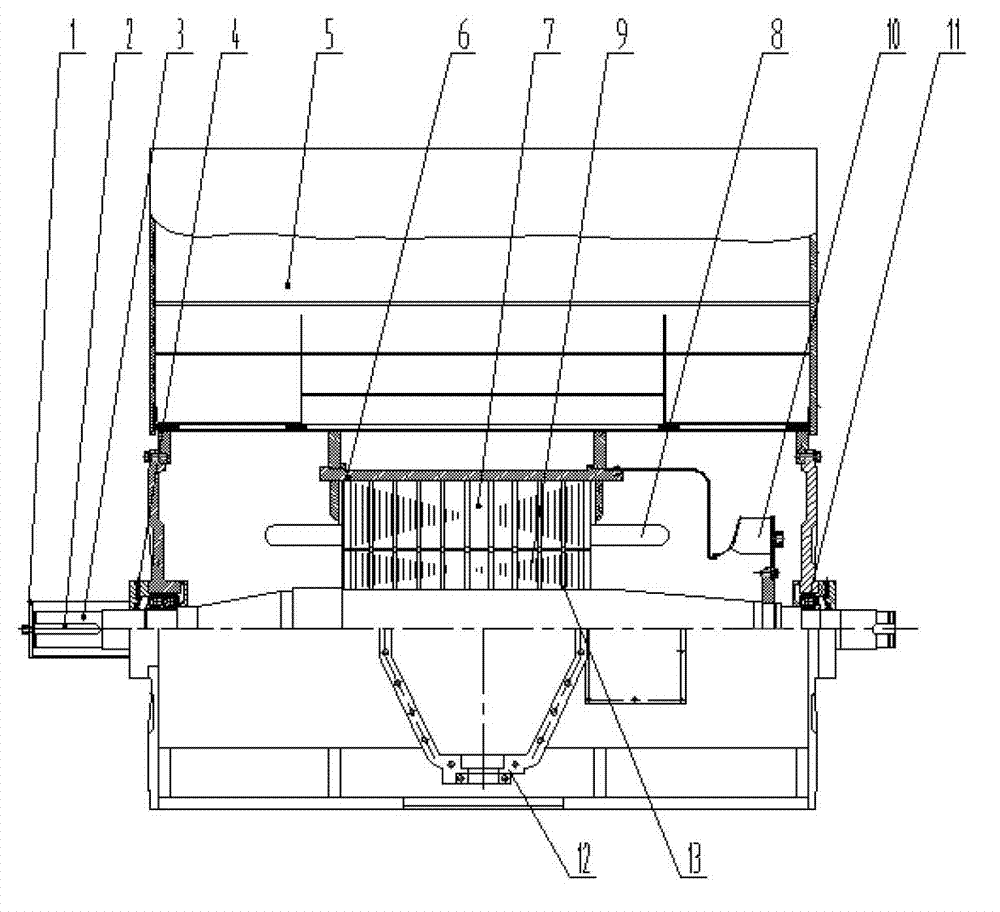
[0030] Please refer to figure 1 As shown, taking the 24 / 16 three-phase switched reluctance motor as an example, the switched reluctance motor with cast aluminum rotor structure of the present invention includes a casing 6, a rotating shaft 3, a stator core 7, a stator winding 8 and a rotor core 9, It can also include a shaft extension protective cover 1, a key 2, a front bearing assembly 4, a cooling fan 5, a cooling fan 10, a rear bearing assembly 11, a motor outlet box 12, and a cooling air duct 13.

[0031] Below to figure 1 The left end shown is the front end, and the structural composition of the generator of the present invention is described.

[0032] The rotating shaft 3 runs through the housing 6 and is rotatably connected to the housing 6 through the front bearing assembly 4 and the rear bearing assembly 11 . The rotor core 9 is installed on the rotating shaft 3 and is located between the front bearing assembly 4 and the rear bearing assembly 11 . The stator core ...


PUM


Abstract

The invention relates to a switched reluctance motor of a cast-aluminum rotor structure. The switched reluctance motor comprises a shell, a rotary shaft, a stator iron core, a stator winding and a rotor iron core. The rotary shaft penetrates through the shell and is rotatably connected with the shell. The stator iron core is fixedly mounted in the shell. The stator winding is an integral pitch winding and mounted in a forming groove of the stator iron core. The rotor iron core is fixedly mounted on the rotary shaft, located in the shell, aligned with the stator iron core, and provided with motor air gaps along the radial direction of the stator iron core. By the switched reluctance motor, power output density of the switched reluctance motor is improved, effective material utilization rate and power factors are improved, vibration, noise, weight and cost of the switched reluctance motor are reduced, competitive advantages of the switched reluctance motor in the field of speed regulating especially in application filed of direct drive wind power generation, and accordingly traditional switched reluctance motors can be replaced widely, and the switched reluctance motor is applicable to the fields of speed regulating and power generation, especially direct drive wind power generation.

Description

technical field [0001] The invention relates to the technical field of generators, in particular to a switched reluctance motor with a cast aluminum rotor structure. Background technique [0002] The switched reluctance motor has the advantages of simple structure, low cost, reliable operation, flexible control, and superior performance, and the speed control system composed of it has advantages that the AC and DC speed control systems do not have. Therefore, the application prospect of the switched reluctance motor Very broad. [0003] With the continuous development of the wind power industry, wind power technology is also constantly being upgraded and updated, mainly manifested in: increasing the unit capacity of wind turbines, developing new technologies to improve the performance of wind turbines, increasing the utilization rate of wind energy, reducing the cost of wind power, and paying more attention to wind turbines control of the safety and reliability of the syste...

Claims


Application Information

Patent Timeline
Patent Type & Authority Patents(China)
IPC IPC(8): H02K29/00H02K1/16H02K1/22H02K1/20H02K9/04
Inventor 肖珊彩秦明
Owner GUODIAN UNITED POWER TECH
Why Eureka
Try Eureka