
Radiator with temperature-controlled water supply unit

A heat dissipation device and water supply technology, which is applied in the direction of electrical components, semiconductor/solid-state device parts, semiconductor devices, etc., can solve the problems of accelerating air, increasing heat generation of radiators, and affecting heat dissipation performance, etc.

Active Publication Date: 2019-10-08
INST OF ELECTRICAL ENG CHINESE ACAD OF SCI
View PDF3 Cites 0 Cited by
  • Summary
  • Abstract
  • Description
  • Claims
  • Application Information

AI Technical Summary

Problems solved by technology

However, when the structure, volume, and environmental conditions of the radiator remain unchanged, and the power of the device increases, the heat generated by the radiator increases, so that the direction and speed of the hot air convection of the radiator's temperature distribution in the horizontal and vertical directions change, and the turbulent flow directly affects Heat dissipation performance. At this time, the natural cooling convection air heat transfer cannot meet the heat dissipation requirements. Active exhaust air must be adopted to lock the flow direction of hot air and accelerate the air heat convection speed to reduce the temperature of the radiator.

Method used


Image

  • Radiator with temperature-controlled water supply unit
  • Radiator with temperature-controlled water supply unit
  • Radiator with temperature-controlled water supply unit

Examples


Embodiment Construction

[0044] The present invention will be further described below in conjunction with the accompanying drawings and specific embodiments.

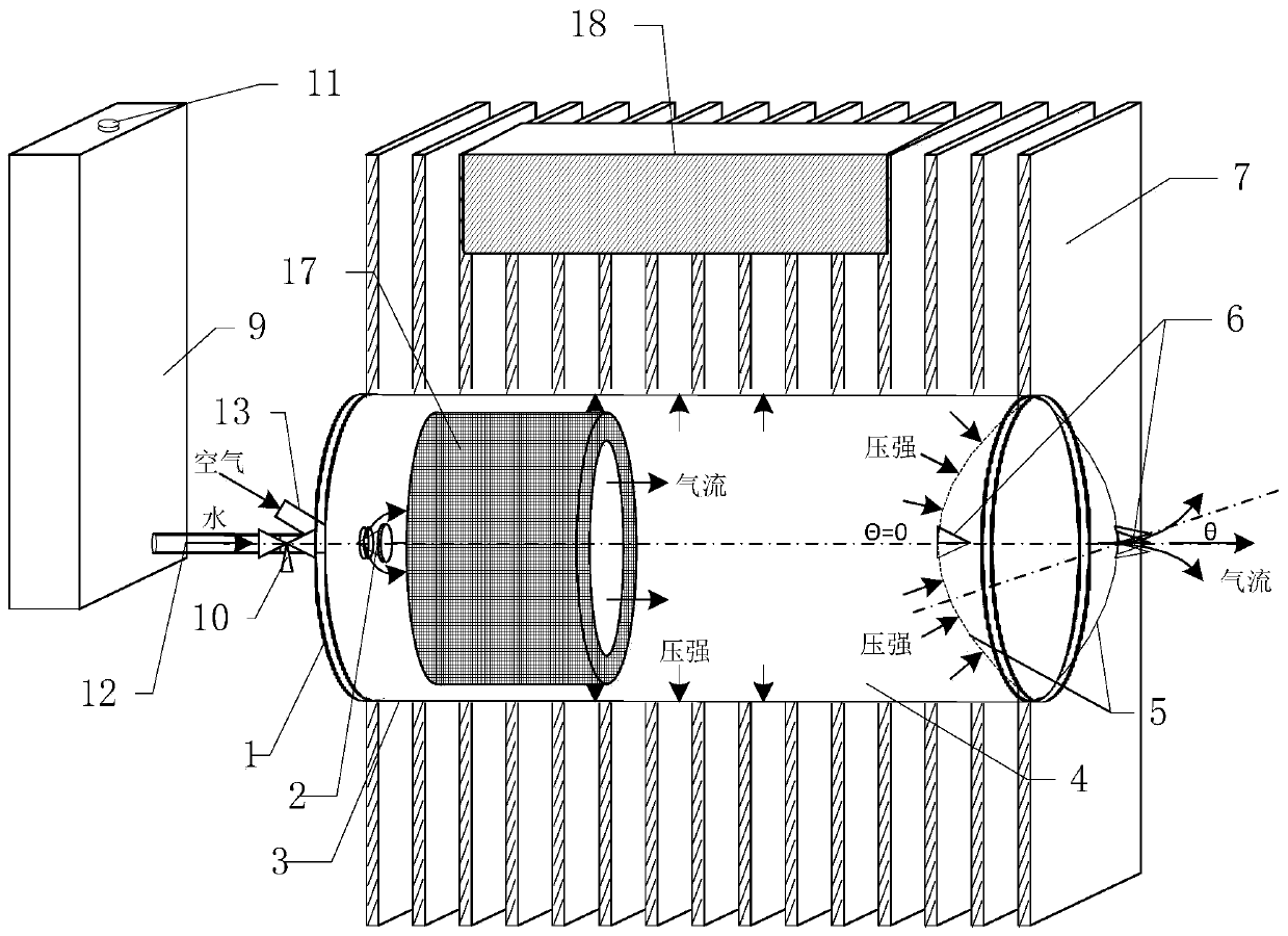
[0045] Such as figure 1 As shown, the cooling device of the present invention is composed of a radiator 7, a device fixing platform 18, a temperature-controlled water supply unit and a breathing unit.

[0046] The water tank 9 in the temperature-controlled water supply unit is separated from the radiator 7 and installed at a position higher than the radiator 7 . The component fixing platform 18 is located on the upper part of the radiator 7, and the breathing unit is embedded in the radiator 7. Power devices that need to be dissipated are fixed on the device fixing platform 18 .

[0047] The water tank 9 in the temperature-controlled water supply unit is connected to the breathing unit through the water guide pipe 12 and the temperature-controlled regulating valve 10, and provides evaporation and cooling water to the breathing unit;

[0048]...


PUM


Abstract

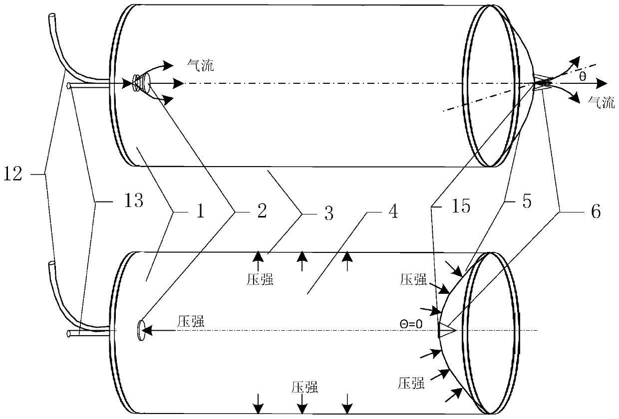
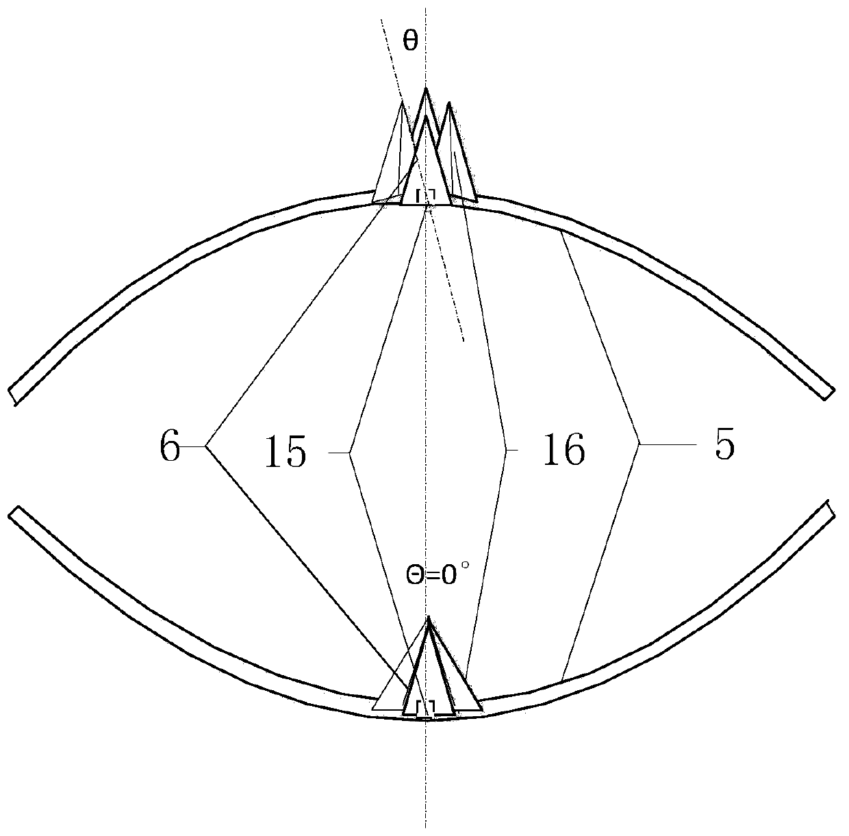
A heat sink with a temperature control and water supply unit includes a radiator (7), a device mounting platform (18), a temperature control and water supply unit and a breathing unit. A water tank (9) is installed at a place higher than the radiator (7), the device mounting platform (18) is installed on the upper part of the radiator (7), and the breathing unit is embedded in the radiator (7) andis tightly matched with the radiator (7). Power devices that require heat dissipation are affixed to the device mounting platform (18). The water tank (9) is connected to the breathing unit through awater conduit (12) and a temperature control valve (10) to provide the breathing unit with water for evaporative heat dissipation. When a pressure greater than the hopping instability point pressureis applied to a truncated spherical hopping diaphragm (5), the truncated spherical hopping diaphragm (5) is recessed downward, a petal curved-surface valve closes, and gas in an expansion unit (4) iscompressed; and the truncated spherical hopping diaphragm (5) is protruded upward, the petal curved-surface valve opens, air or water is sucked, and the gas in the expansion unit (4) is exhausted.

Description

technical field [0001] The invention relates to a heat dissipation device. Background technique [0002] The ubiquitous application of heat dissipation is recognized and accepted by people. Taking power electronic devices as an example, due to the self-loss of power devices, a lot of heat is generated, and the power loss is proportional to the power increase. At present, the heat dissipation methods mainly include: natural cooling, forced exhaust cooling, and water circulation cooling. Its cooling effect, cost, complexity, and energy loss are in order from low to high, and its reliability is in order from high to low, especially for wide-bandgap semiconductor devices with a junction temperature as high as 225°C. The temperature limit of water circulation cooling cannot exert wide-bandgap semiconductor devices. High temperature resistance characteristics of semiconductor devices. Therefore, heat dissipation is one of the key elements affecting the performance and quality o...

Claims


Application Information

Patent Timeline
Patent Type & Authority Patents(China)
IPC IPC(8): H01L23/427H01L23/467H01L23/473
CPCH01L23/427H01L23/467H01L23/473
Inventor 杨子龙王哲曹国恩王一波
Owner INST OF ELECTRICAL ENG CHINESE ACAD OF SCI
Learn More