
Barrel plating automatic washing device

An automatic cleaning and barrel plating technology, applied in cleaning methods and utensils, cleaning methods using liquids, chemical instruments and methods, etc., can solve the problems of unreasonable cleaning water consumption, labor-intensive workers, and only manual operation. Achieve the effect of reducing unreasonable water use, improving industry competitiveness, and saving processing costs

Inactive Publication Date: 2013-04-10
禤伟光
View PDF7 Cites 2 Cited by
  • Summary
  • Abstract
  • Description
  • Claims
  • Application Information

AI Technical Summary

Problems solved by technology

Since the workpieces have to be cleaned several times during cleaning, the physical load of the production workers is heavy, the labor intensity is high, and the process requires a large number of workers, and the industrial wastewater generated during the production process leaks seriously and pollutes the environment.
In the above-mentioned manual cleaning method, the sewage generated during workpiece cleaning cannot be collected and discharged. In the barrel plating workshop, sewage always leaks out at the position where the workpiece is cleaned, polluting the environment
At the same time, due to the inaccurate control of water consumption in manual operations, the unreasonable increase in water consumption for cleaning increases production costs
Due to structural defects, the equipment used for cleaning the above-mentioned electroplated workpieces can only be operated manually and cannot be cleaned automatically. The labor intensity of the workers is high, the production efficiency is low, and the waste liquid generated pollutes the environment.

Method used


Image

  • Barrel plating automatic washing device
  • Barrel plating automatic washing device
  • Barrel plating automatic washing device

Examples


Embodiment Construction

[0020] With reference to the accompanying drawings, its structure is described in detail.

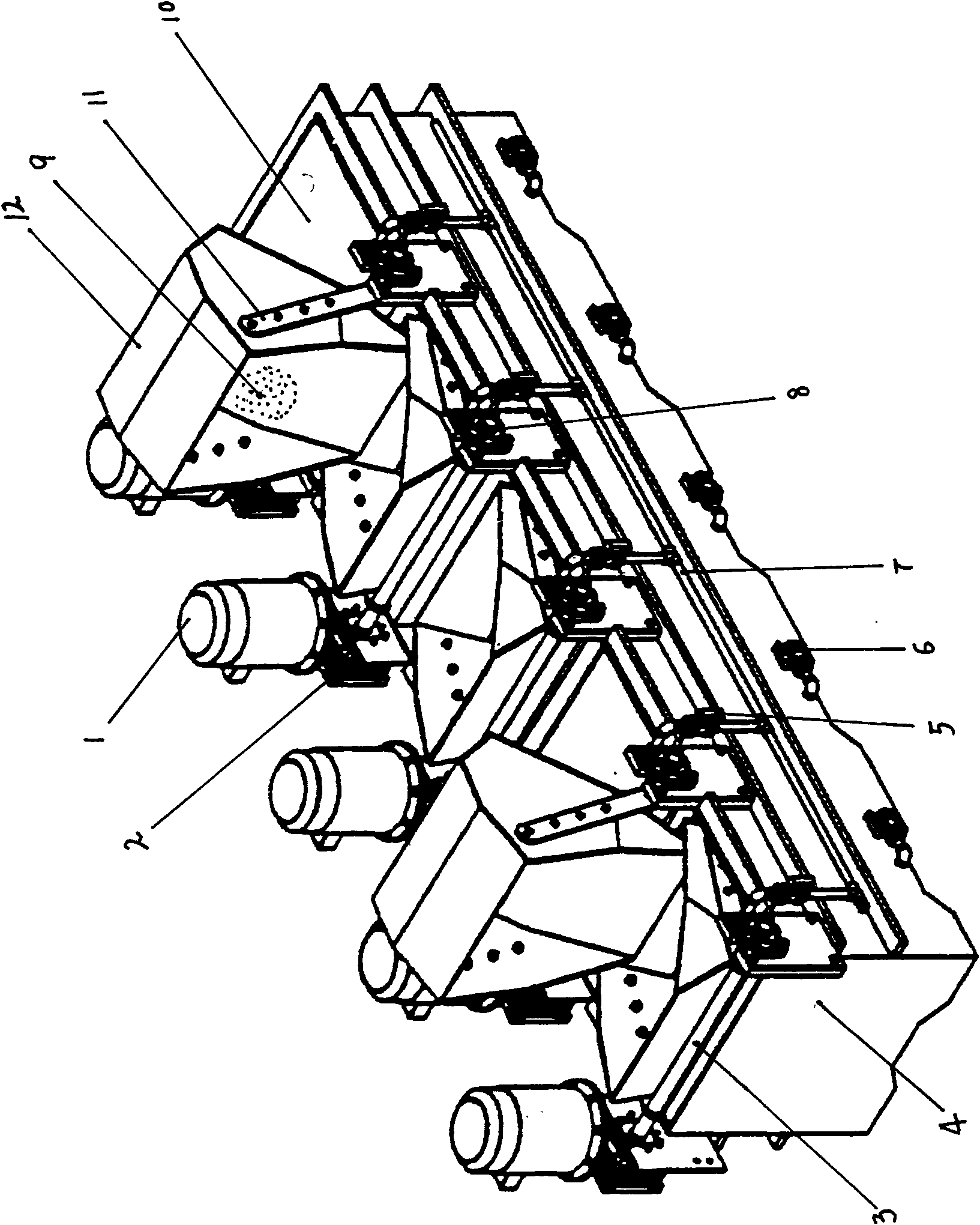
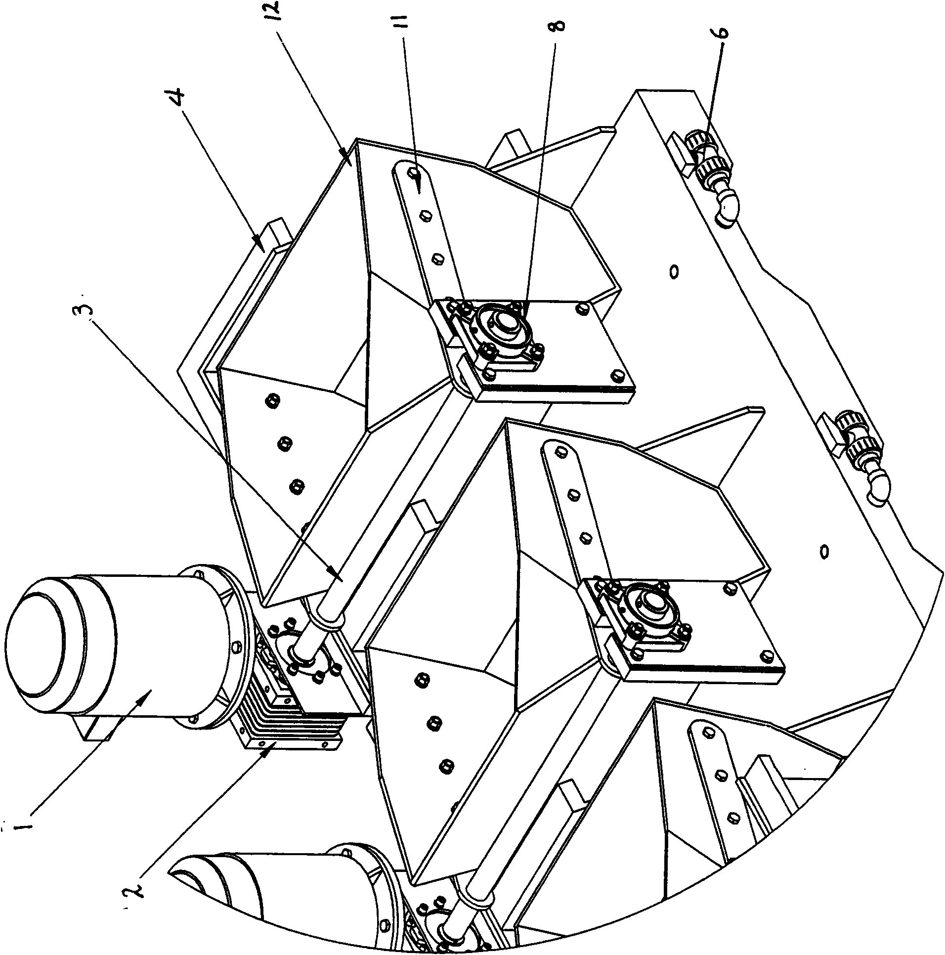
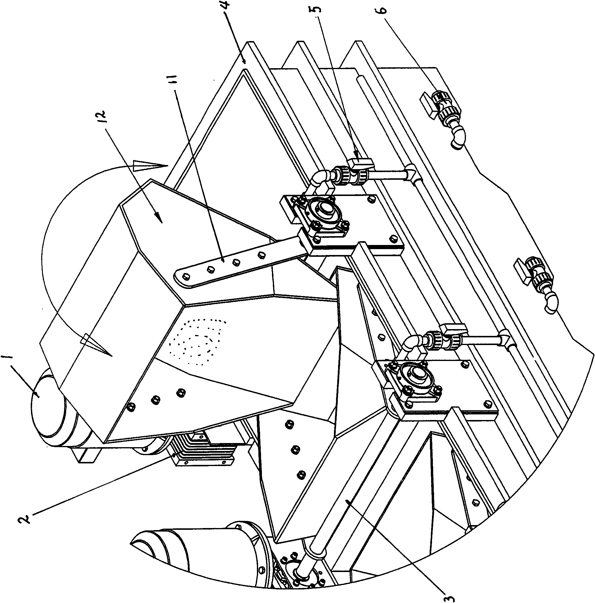
[0021] exist Figure 1~3 Among them, the tank body 4 of this cleaning device is a conjoined tank body, and several cleaning tanks 10 are arranged in the tank body, and the cleaning liquid in each cleaning tank is not connected to each other, and a hopper 12 and a turning device are arranged on the tank body, and the turning device includes a motor , a gearbox, a rotating shaft and a swing arm, the hopper 12 is fixed on the rotating shaft 3 through the swing arms 11 installed on both sides of the hopper, a motor 1 and a gearbox 2 are arranged on the frame of the tank body 4 on one side, and the other side The frame is provided with a bearing seat 8, the motor shaft is connected with the gearbox, and one end of the rotating shaft is installed on the bearing seat, and through the power transmission of the motor rotation and the gearbox, the rotating shaft drives the hopper to rotate (turn ...


PUM


Abstract

The invention relates to a barrel plating automatic washing device. The barrel plating automatic washing device comprises a tank body, hoppers, motors, gearboxes, rotating shaft rods, water inlet valves and drain valves. The tank body is a one-piece tank body. A plurality of washing pools are arranged in the tank body. The hoppers and an overturning device are arranged on the tank body. The hoppers are fixed on the rotating shaft rods through swing arms. One ends of the rotating shaft rods are installed on the gearboxes, and the other ends of the rotating shaft rods are installed on bearing supports. Through motor rotation and power transmission of the gearboxes, the rotating shaft rods drive the hoppers to rotate together, and therefore the purpose of automatic cleaning is achieved. According to the barrel plating automatic washing device, overturning of the motors and the hoppers and flow rates of cleaning fluid are controlled by a computer controller, the degree of automation is high, washing efficiency is high, water consumption quantities are accurately controlled, labor intensity of workers is greatly relieved, workshop working environment is cleaned, and the barrel plating automatic washing device has popularization prospects.

Description

technical field [0001] The invention relates to barrel plating cleaning equipment in the electroplating industry, in particular to an automatic barrel plating cleaning device, which belongs to the technical field of environmental protection and energy saving products. Background technique [0002] In the electroplating industry, electroplated workpieces must be cleaned before they can be used. In the current barrel plating operation in the electroplating industry, the cleaning of the workpiece after electroplating is generally to place a cleaning solution in a simple plastic tank to clean the workpiece manually. In this manual cleaning method, the workpiece must be cleaned several times before it can be cleaned. Since the workpieces have to be cleaned several times during cleaning, the physical load of the production workers is heavy, the labor intensity is high, and the process requires a large number of workers, and the industrial wastewater generated during the productio...

Claims


Application Information

Patent Timeline
Patent Type & Authority Applications(China)
IPC IPC(8): B08B3/04
Inventor 禤伟光程志成
Owner 禤伟光
Learn More