
Punching and electric spark combined micro arrayed through hole machining method and device

A processing method and electric spark technology are applied in the field of micro-array through-hole processing, which can solve the problems of reduced processing efficiency and accuracy, easy formation of taper, and large corrosion, and achieves improved mutual position accuracy, increased hardness and strength, and reduced manufacturing. cost effect

Active Publication Date: 2015-04-22
苏州新实达精密电子科技有限公司
View PDF7 Cites 0 Cited by
  • Summary
  • Abstract
  • Description
  • Claims
  • Application Information

AI Technical Summary

Problems solved by technology

[0004] However, micro-ultrasonic machining is only suitable for hard and brittle materials, and the axial dimension is difficult to control; laser processing and electron beam processing are expensive, the equipment is expensive, the hole shape is slightly waist-tapered, and the laser-processed parts have a recast layer, and the surface quality is poor. Poor; micro-electrolytic machining has large stray corrosion, low precision, and corrosion to fixtures and machine tools; LIGA technology has a large investment and complicated machining process; micro-EDM mainly has machining short circuit, open circuit or arc discharge, which reduces machining efficiency and accuracy , In addition, there are problems such as electrode loss, difficult tool compensation, and slow processing speed during processing, and the processed holes are easy to form a taper; the workpiece is deformed in microplastic forming processing, and is limited by the size of the tool, it is difficult to process a small group of holes structure, and the requirements for the preparation and clamping of the punch are also very high

Method used


Image

  • Punching and electric spark combined micro arrayed through hole machining method and device
  • Punching and electric spark combined micro arrayed through hole machining method and device

Examples


Embodiment Construction

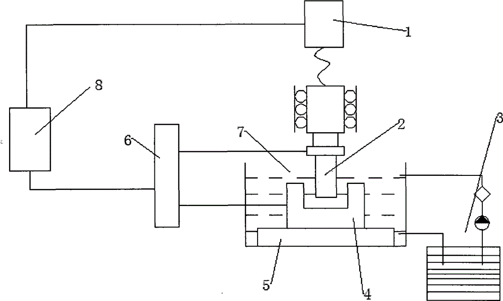
[0026] The present invention will be described in further detail below in conjunction with the accompanying drawings and specific embodiments.

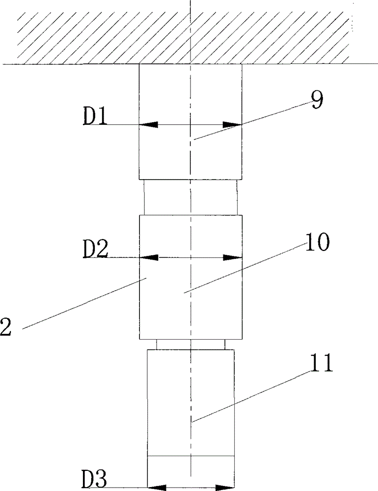
[0027] Such as figure 1 As shown, the forming die 2 used in the micro-array through-hole processing method based on punching and EDM is a three-stage type, which consists of electrodes 11, punches 10 and grinding tools 9 from top to bottom, and the electrode diameter is D3 , There is the following relationship between the punch diameter D2 and the abrasive tool diameter D1: D3<D2<D1, and D2=D3+(2~6μm), D1=D2+(0.05~0.5μm), electrode length L3, punch length There is the following relationship between L2, grinding tool length L1 and workpiece thickness t: L3=5 / 6×t, L2=(1.01~0.99)×t, L1=(1.01~1)×t; coated electrode 11 and the grinding tool 9, uniformly deposit a layer of metal layer with good wear resistance on the outer surface of the punch 10 by electrolytic deposition, and the thickness of the deposited metal layer is 1-20 μm; coat th...


PUM

PropertyMeasurementUnit
thicknessaaaaaaaaaa

Abstract

The invention relates to the field of micro hole machining, in particular to a punching and electric spark combination-based micro arrayed through hole machining method and a punching and electric spark combination-based micro arrayed through hole machining device. The advantages of the conventional punching machining and the conventional electric spark machining are integrated, and an adopted forming head is divided into three sections, i.e. an electrode for the electric spark machining, a punch for punching and a grinding tool for precision grinding. The method comprises the following steps of: performing die cavity machining on holes by using an electrode section of the forming die head, switching off a direct current generator when the lower end of the electrode is only 1 / 6t to 1 / 7t (t is the thickness of a plate) away from the bottom of the plate, directly punching the plate at certain speed by using a punch section of the forming die head, and after the plate is punched, enabling the grinding tool of the forming die head to move up and down to realize a precision grinding function. The method and the device are rational in design, high in practicability and suitable for the low-cost batch production of micro arrayed through holes.

Description

technical field [0001] The invention belongs to the field of micro-forming technology, and specifically refers to a method and device for processing micro-array through holes combined with punching and electric discharge, which combines the advantages of micro-punching and micro-electric discharge machining, and uses the method to process micro-through holes. It avoids the taper hole caused by EDM, and also avoids the problem of easy damage to the punch due to excessive punching force, and can achieve high efficiency, low cost, large batches, and high precision. Background technique [0002] In industrial fields such as micro-array holes, more and more components are used as the key structure (such as optical fiber connectors, electrical connectors, chemical fiber spinnerets, inkjet holes for printers, integrated circuit boards, electron microscope gratings, micro Nozzle, filter plate and other structures), the processing requirements are getting higher and higher, the gener...

Claims


Application Information

Patent Timeline
Patent Type & Authority Patents(China)
IPC IPC(8): B23H9/14B23H5/04
Inventor 王匀陆广华许桢英殷苏民王雪鹏吴俊峰蒋素琴陈万荣
Owner 苏州新实达精密电子科技有限公司
Learn More