Back spindle automatic discharging device

A technology of automatic discharge and spindle, applied in the direction of positioning device, clamping, support, etc., can solve the problems of complicated operation procedures and affect processing efficiency, and achieve the effect of avoiding human error, good discharge effect and high precision.

Inactive Publication Date: 2013-04-10
陈胜喜
View PDF1 Cites 4 Cited by
  • Summary
  • Abstract
  • Description
  • Claims
  • Application Information

AI Technical Summary

Problems solved by technology

[0004] Although this device can complete the automatic clamping of the workpiece, the discharge process requires manual operation, and the operation procedure is relatively complicated, which seriously affects the processing efficiency

Method used


Image

  • Back spindle automatic discharging device

Examples


Embodiment Construction

[0015] Below in conjunction with accompanying drawing description and specific embodiment, the present invention will be described in further detail:

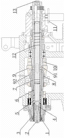
[0016] see figure 1 , an automatic discharge device for the back spindle, comprising a collet 1, a ejector pin 2, a collet cover 3 and a bar material inlet 13, the ejector pin 2 is located in the collet 1, and the collet 1 is located in the collet sleeve 3, and one end of the ejector pin 2 is threaded, and the ejector pin 2 is threadedly connected with the push rod-4, and the length of the ejector pin 2 can be appropriately changed according to needs, but it should not be too long , otherwise it will affect the clampable length of the bar, the collet sleeve 3 is threaded with the limit sleeve 6, and a return spring 5 is arranged between the collet 1 and the limit sleeve 6, and the return spring 5 The cross-section of the chuck is rectangular to ensure the reliable reset of the collet cover. One end of the collet cover 3 near t...


PUM


Abstract

The invention relates to a back spindle automatic discharging device which comprises an elastic chuck, an ejector pin, a chuck sleeve and a bar feed inlet. The ejector pin is positioned in the elastic chuck; the elastic chuck is positioned in the chuck sleeve; the ejector pin is in threaded connection with a first push rod; the chuck sleeve is in threaded connection with a limiting sleeve; a return spring is arranged between the elastic chuck and the limiting sleeve; one end of the chuck sleeve, which is close to the bar feed inlet, is in contact with a second push rod; the other end of the second push rod is in contact with a short arm of an opening and closing jaw; a long arm of the opening and closing jaw is in contact with a pneumatic actuator; an ejector spring is arranged between the elastic chuck and the bar feed inlet; and one side of the bar feed inlet is provided with an inductive switch. According to the invention, functions of automatically clamping and discharging a back spindle are implemented; and the back spindle automatic discharging device is simpler and more convenient to operate and has higher processing efficiency.

Description

technical field [0001] The invention relates to a discharge device, in particular to an automatic discharge device for a back spindle. Background technique [0002] Today, with the needs of processing, the application of back spindles on machine tools, especially CNC lathes, is becoming more and more extensive. The application of back spindles greatly reduces the clamping time of workpieces, improves the machining accuracy of workpieces, and significantly expands the processing of CNC machine tools. scope. [0003] The Chinese patent authorization announcement number is CN 2659602Y, and the utility model patent with the authorization announcement date on December 1, 2004 discloses an adjustable precision clamping spindle, including a spring chuck used to clamp the workpiece and a clamping chuck connected to the chuck. The mandrel and the support sleeve used to support the clamping mandrel, the large diameter of the clamping mandrel is fixedly connected to a main shaft head,...

Claims


Application Information

Patent Timeline
Patent Type & Authority Applications(China)
IPC IPC(8): B23Q3/12B23Q7/00
Inventor 陈胜喜
Owner 陈胜喜
Why Eureka
Try Eureka