Supercharge Your Innovation With Domain-Expert AI Agents!

Feeding and conveying systems for conveying jigs and heat treatment industrial furnaces

A technology for fixtures and transmission direction, which is applied in the direction of thin material processing, lighting and heating equipment, furnaces, etc. It can solve the problems of difficult tension control, complex structure of transmission fixtures, and uninterrupted transmission, so as to reduce the difficulty of control and realize intermittent transmission. The effect of transmission and simplification of the structure

Active Publication Date: 2015-12-16
SHANGHAI SHENGMAO CONTROL EQUIP
View PDF5 Cites 0 Cited by
  • Summary
  • Abstract
  • Description
  • Claims
  • Application Information

AI Technical Summary

Problems solved by technology

[0003] The technical problem to be solved by the present invention is to provide a transmission jig to overcome the defects of the prior art transmission jig with complex structure, difficult tension control, easy damage to the workpiece, and inability to transmit intermittently.

Method used


Image

  • Feeding and conveying systems for conveying jigs and heat treatment industrial furnaces
  • Feeding and conveying systems for conveying jigs and heat treatment industrial furnaces
  • Feeding and conveying systems for conveying jigs and heat treatment industrial furnaces

Examples


Embodiment 1

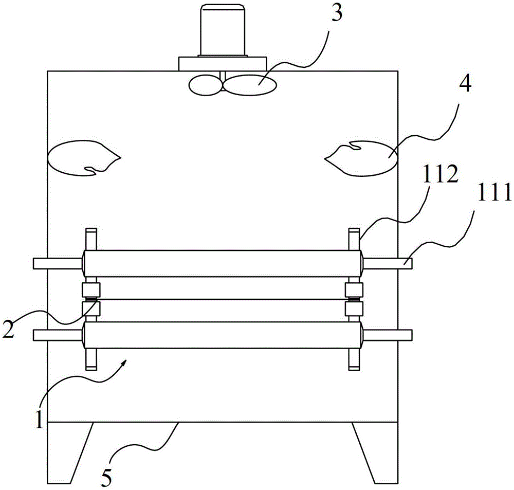
[0031] Such as figure 1 As shown, this embodiment includes a conveying device 1 , a workpiece 2 , a circulating fan 3 , a heating device 4 , and a furnace 5 .

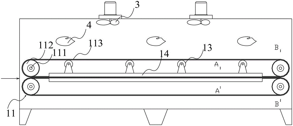
[0032] Such as figure 2 As shown, the transmission device 1 includes two groups of sprocket mechanisms 11 up and down, and each sprocket mechanism 11 includes two chains 113 arranged on both sides. The chain drive has many advantages: no elastic sliding and slipping phenomenon, average transmission ratio Accurate, reliable, high efficiency; large transmission power, strong overload capacity, small transmission size under the same working conditions; small tension required, small pressure on the shaft; can be used in high temperature, humidity, dusty, Work in harsh environments such as pollution.

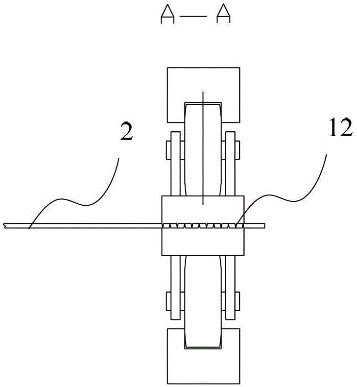
[0033] Such as image 3 or Figure 4 As shown, the clamp 12 is used to clamp the workpiece 2 . Clamp 12 is connected on the 11 chains 113 of sprocket mechanism, and under the drive of sprocket mechanism 11, chain 113 to...

Embodiment 2

[0042] The difference between this embodiment and Embodiment 1 is that, in this embodiment, there is only one set of sprocket mechanism 11, and such arrangement can further simplify the mechanism. Correspondingly, this embodiment adopts such as Figure 6 Fixture 12 shown. Fixture 12 is a plurality of needle-nose pliers, each of which includes a jaw for clamping the workpiece, and a handle for controlling the opening and closing of the jaw, each of which is connected to a chain 113 fixed inside. In this way, the clamp 12 can clamp the workpiece 2 by itself, without the need to clamp the workpiece 2 under the clamping of the upper and lower chains 113 . The other parts of this embodiment are all the same as in Embodiment 1.

Embodiment 3

[0044] The difference between this embodiment and Embodiment 1 is that in this embodiment, the feeding and conveying system of the heat treatment industrial furnace includes two sets of conveying fixtures, such as Figure 7As shown, in this way, the relay transfer of the workpiece can be realized when the length of the path is long. The other parts of this embodiment are all the same as in Embodiment 1.


PUM


Abstract

The invention discloses a conveying fixture and a material feeding and conveying system of a heat treatment industrial furnace. The conveying fixture comprises two groups of fixtures and a conveying device, wherein the fixtures are used for clamping workpieces and conveying the workpieces in a conveying direction, and the conveying device is connected with the fixture and used for driving the fixture to rotate; the conveying device is used for enabling the fixtures to move in the conveying direction; and each group of fixtures is used for respectively clamping the edges of the two opposite sides of the workpiece in the conveying direction. Through the adoption of the conveying fixture disclosed by the invention, the structure of the conveying fixture can be simplified, the control difficulty and damage to the workpieces are reduced, and the workpieces can be discontinuously conveyed.

Description

technical field [0001] The invention relates to a conveying jig and a feeding and conveying system of a heat treatment industrial furnace. Background technique [0002] The current conveying jigs adopt idler roller and mesh belt feeding method, which has complex structure and high cost, and has high requirements for tension control roller, and there are many tension control points, which makes it difficult to control feeding and tension, which is easy to cause Metal thin materials vary in thickness. Especially when transferring the metal plate, since the entire surface of the metal plate will be under the pressure of the mesh belt, it will cause damage to the metal surface. The design of the idler also makes it impossible for the transfer jig to realize the intermittent transfer of the workpiece. Contents of the invention [0003] The technical problem to be solved by the present invention is to provide a transmission jig to overcome the defects of the prior art transmis...

Claims


Application Information

Patent Timeline
Patent Type & Authority Patents(China)
IPC IPC(8): B65H5/02F27B9/24F27B9/30
Inventor 乔京涛
Owner SHANGHAI SHENGMAO CONTROL EQUIP
Features
  • R&D
  • Intellectual Property
  • Life Sciences
  • Materials
  • Tech Scout
  • Unparalleled Data Quality
  • Higher Quality Content
  • 60% Fewer Hallucinations
Learn More