Low-position vacuum preloading rapid reinforcement method of soft foundation in hydraulic filling and reclamation
A soft foundation, land reclamation technology, applied in soil protection, infrastructure engineering, construction, etc.
- Summary
- Abstract
- Description
- Claims
- Application Information
AI Technical Summary
Problems solved by technology
Method used
Image
Examples
Embodiment 1
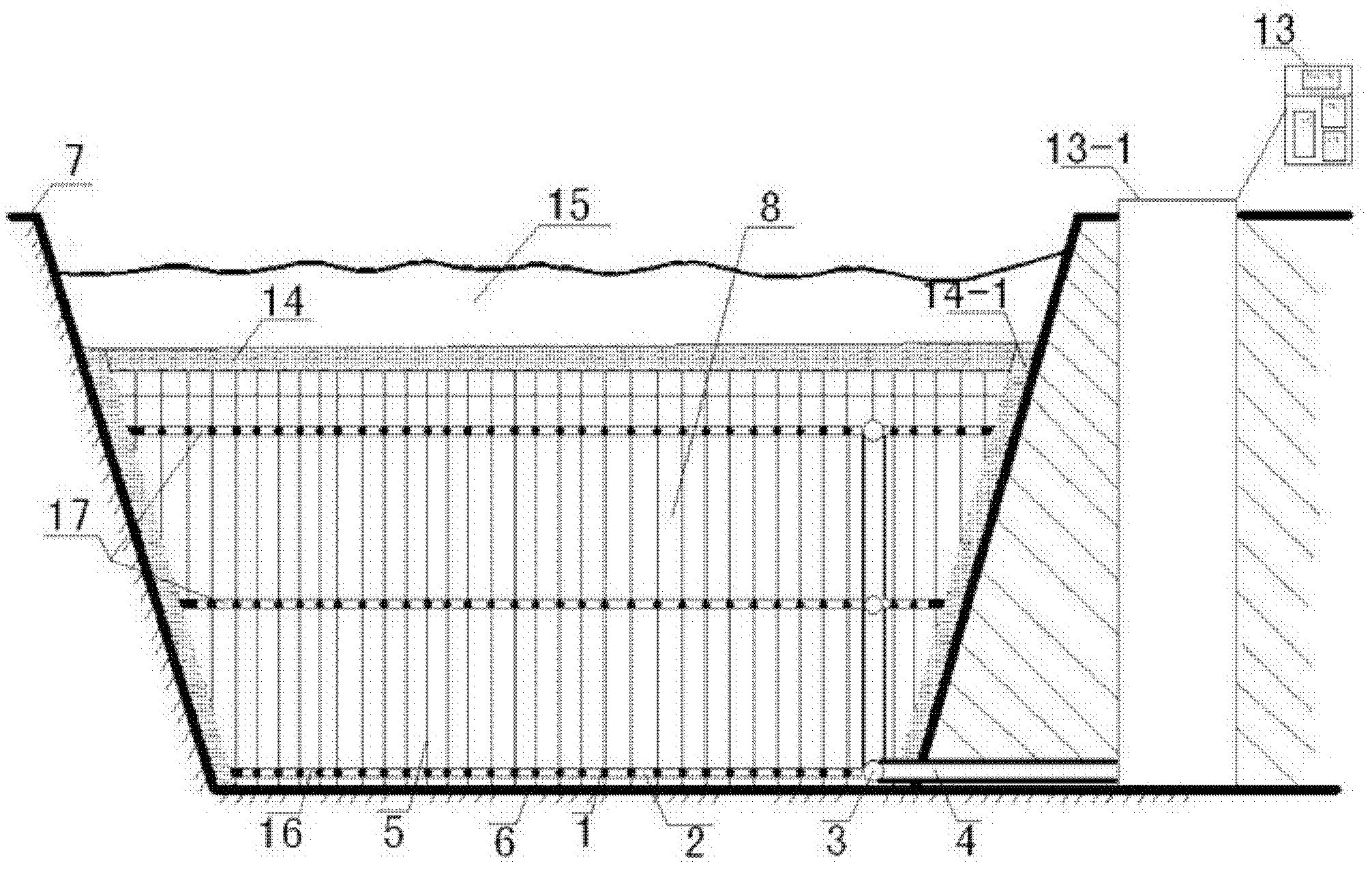
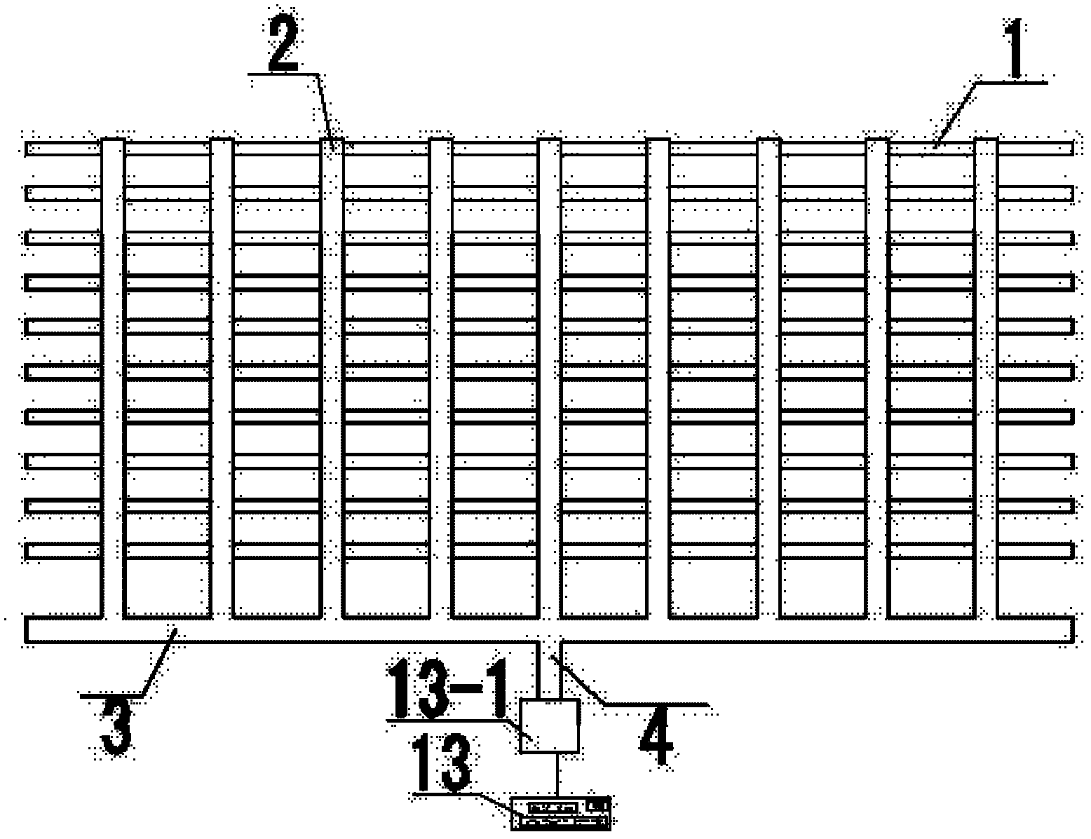
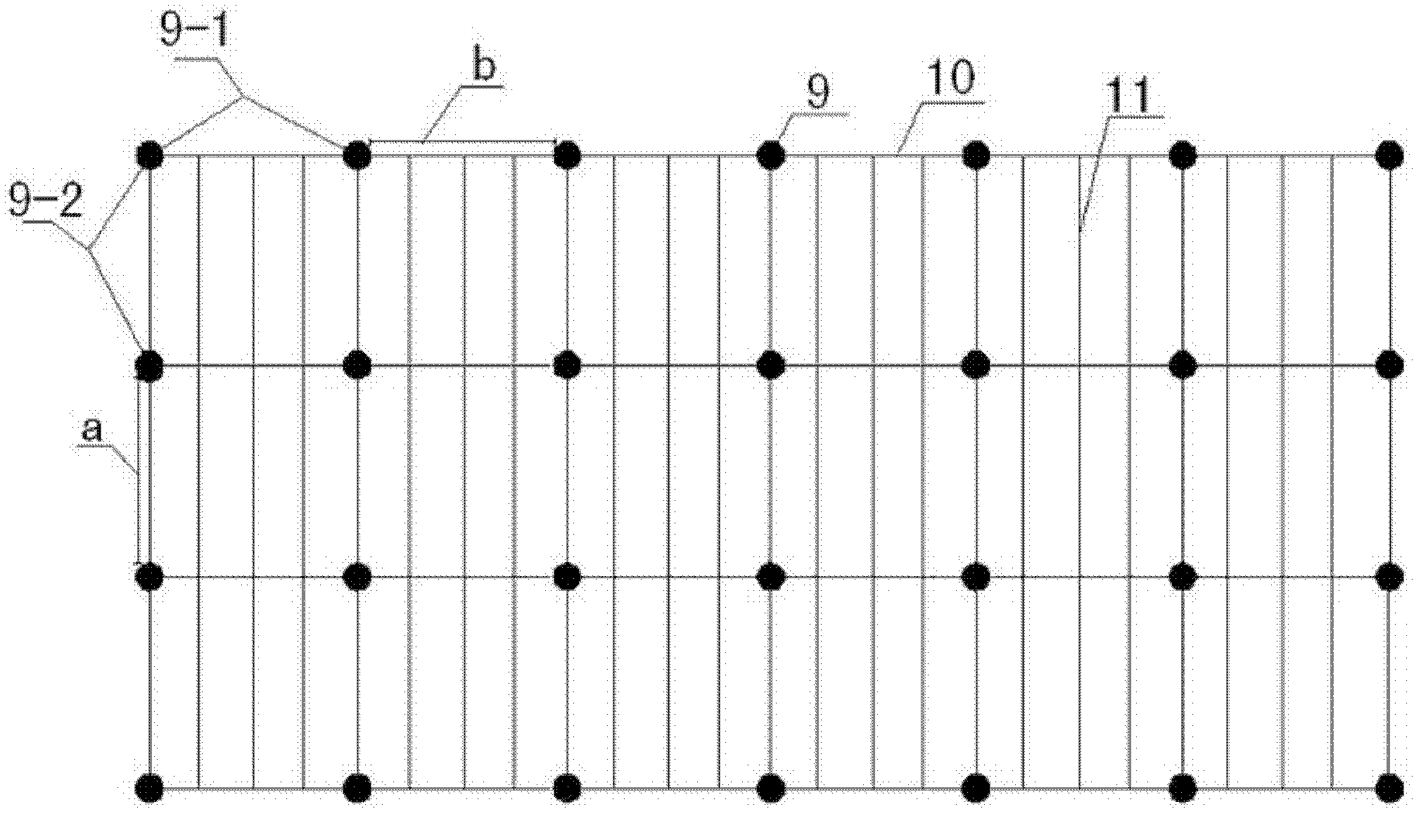
[0074] When the final dredging design elevation is 1m, according to the attached Figure 1-5 As shown in the content, only the bottom drainage pipe network can be set to meet the needs of drainage consolidation. The specific technical scheme is as follows
[0075] 1. The layout of the bottom drainage pipe network
[0076] Before the dredging and filling of sludge, the laying of the bottom drainage pipe network 16 is carried out. The spacing of the permeable holes 12 on the surface of the drain pipe is 2m. In order to prevent the entry of mud, the outer surface of the permeable hole on the drain pipe is wrapped with non-woven fabric. On the ground surface 6 of the area to be filled, a commercially available conventional drainage board 5 and the permeable hole of the drainage pipe 1 are used for wrapping and fixing.
[0077] The horizontal spacing b of adjacent brackets in the single row of brackets in the drainage pipe network is 2m, and the horizontal row spacing a of adja...
Embodiment 2
[0093] When the final dredging design elevation is 1.5m, according to the attached Figure 1-5 The content shown is set to a total of two layers of drainage pipe network, the bottom layer and the upper layer. The specific technical scheme is as follows:
[0094] 1. The layout of the bottom drainage pipe network
[0095] Before dredging and filling the sludge, lay out the bottom drainage pipe network according to the method of Example 1. The distance between the permeable holes 12 on the surface of the drainage pipe is 3m, the horizontal distance between adjacent drainage pipes is 6m, and the horizontal distance between adjacent drainage branch pipes is 30m.
[0096] 2. Arrangement of brackets
[0097] Before dredging and filling the mud, the ground surface 6 of the area to be filled is horizontally set up supports 9 side by side. The bracket is composed of three bamboo poles, the lower ends of which are inserted into the ground surface, and the upper ends of the brackets i...
Embodiment 3
[0113] When the final dredging design elevation is 4m, according to the attached Figure 1-5 The content shown is set to a total of two layers of drainage pipe network, the bottom layer and the upper layer. The specific technical scheme is as follows:
[0114] 1. The layout of the bottom drainage pipe network
[0115] Before dredging and filling the sludge, lay out the bottom drainage pipe network according to the method of Example 1. The distance between the permeable holes 12 on the surface of the drainage pipe is 1.5m, the horizontal distance between adjacent drainage pipes is 4m, and the horizontal distance between adjacent drainage branch pipes is 20m.
[0116] 2. Arrangement of brackets
[0117] Before dredging and filling the mud, the ground surface 6 of the area to be filled is horizontally set up supports 9 side by side. The bracket is composed of three metal pipes, the lower ends of which are inserted into the ground surface, and the upper ends of the brackets in...
PUM
 Abstract
Description
Claims
Application Information
 - R&D
- Intellectual Property
- Life Sciences
- Materials
- Tech Scout
- Unparalleled Data Quality
- Higher Quality Content
- 60% Fewer Hallucinations
Browse by: Latest US Patents, China's latest patents, Technical Efficacy Thesaurus, Application Domain, Technology Topic, Popular Technical Reports.
© 2025 PatSnap. All rights reserved.Legal|Privacy policy|Modern Slavery Act Transparency Statement|Sitemap|About US| Contact US: help@patsnap.com


