On-line real-time monitoring method and device for failure of hydraulic motor of large-sized plate bending roll

A hydraulic motor, real-time monitoring technology, applied in the direction of fluid pressure actuation device, fluid pressure actuation system test, mechanical equipment, etc., can solve the problems of equipment output power reduction, becoming load, transmission component damage, etc., to achieve reliability And the effect of life improvement, reasonable design, and guaranteed stability

Active Publication Date: 2013-04-10
TAIAN HUALU METALFORMING MACHINE TOOL
4 Cites 13 Cited by

AI-Extracted Technical Summary

Problems solved by technology

[0003] When the plate rolling machine is working, all the work rolls are loaded, and the hydraulic motors that provide torque for the plate rolling are frequently started and have impact loads. When one or more hydraulic motors fail, the faulty motor will not only fail If it becomes power, it will become a load instead, reducing the output power of the equipment
At the same time, it will cause serious damage to the t...

Abstract

The invention discloses an on-line real-time monitoring method for failure of a hydraulic motor of a large-sized plate bending roll. The on-line real-time monitoring method comprises a hydraulic transmission part and a micro control part, wherein the hydraulic transmission part comprises a plurality of groups of high-pressure oil pumps and an oil pump motor, an electromagnetic overflow valve and a hydraulic motor thereof, two-way cartridge valves and a pipeline; the micro control part comprises an industrial personal computer, a PLC (Programmable Logic Controller), a pressure sensor, a bidirectional flow detector and a peripheral circuit; oil pressures and flow rates of oil inlet and outlet paths of the hydraulic motor are detected, and signals are transmitted to the PLC by the pressure sensor and the bidirectional flow detector, are then transmitted to the industrial personal computer by the PLC and are compared with standard parameter values in an industrial personal computer database; and an alarm is automatically sent out and the operation is stopped when the failure of the hydraulic motor is judged. According to the on-line real-time monitoring method, the problem that the failure of a transmission system of the hydraulic motor can only be judged afterwards and cannot be warned early is solved, so that the reliability of the plate bending roll is greatly improved and the life of the plate bending roll is greatly prolonged.

Application Domain

Technology Topic

Image

  • On-line real-time monitoring method and device for failure of hydraulic motor of large-sized plate bending roll
  • On-line real-time monitoring method and device for failure of hydraulic motor of large-sized plate bending roll
  • On-line real-time monitoring method and device for failure of hydraulic motor of large-sized plate bending roll

Examples

  • Experimental program(1)

Example Embodiment

[0017] The specific embodiments of the present invention are described below in conjunction with the drawings:
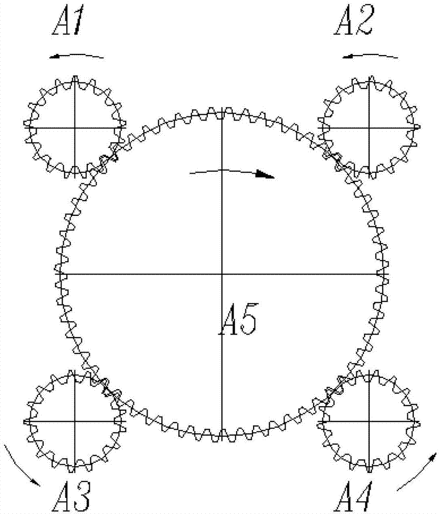
[0018] figure 1 Shown is a schematic diagram of the structure when four hydraulic motors simultaneously drive a rotating device. Four driving gears are installed on the output shafts of the four hydraulic motors, namely A1, A2, A3, and A4. The four driving gears A1, A2, A3, and A4 simultaneously drive a driven gear A5. This is a general and typical situation where multiple hydraulic motors simultaneously drive a rotating part. The present invention takes this example as an illustration, and its protection scope is not limited by the specific number of hydraulic motors.
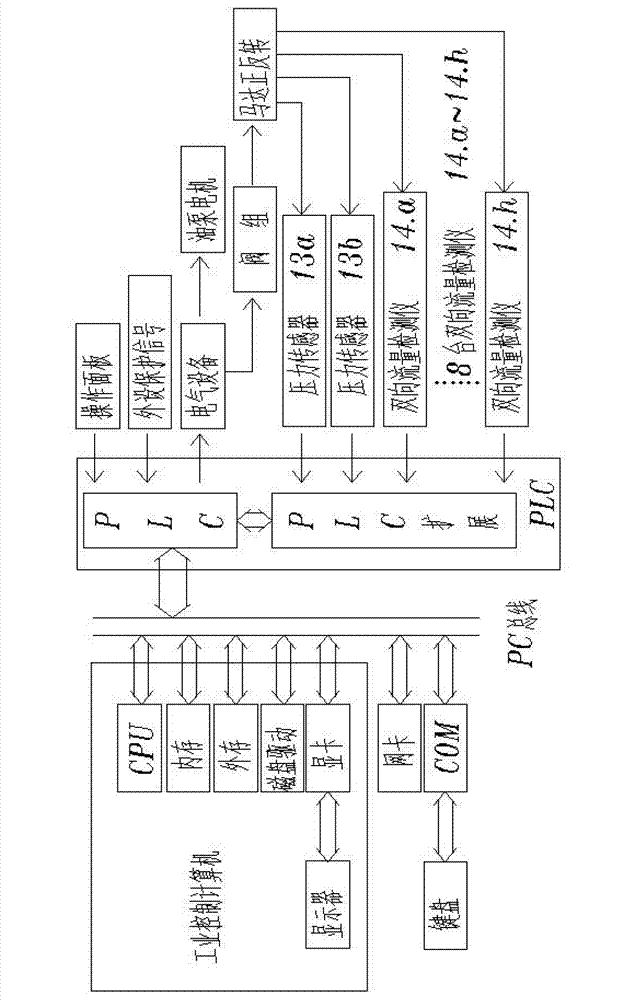
[0019] figure 2 It is the structure diagram of the industrial computer and PLC communication sampling of the present invention. The figure shows that the pressure and flow signals are collected and processed by PLC, and then uploaded to the upper computer—industrial computer through communication. At the same time, the industrial computer also downloads the parameters set by the system to the lower computer—PLC. The PLC receives the instructions on the operation panel, and the output unit of the PLC drives the peripheral electrical equipment to work, thereby driving the oil pump motor and the hydraulic valve group to act, and then driving the hydraulic motor to rotate forward and backward through the change of the hydraulic oil flow direction.
[0020] image 3 Shown is the schematic diagram of the hydraulic system structure, marked in the figure: oil tank 1; high-pressure ball valve 2; shock throat 3; oil pump motor 4; high-pressure oil pump 5; pipeline filter 6; electromagnetic overflow valve 7; one-way valve 8; Two-way cartridge valves 9, 10, 11, 12; pressure sensor 13; two-way two-way flow detector 14; balance valve 15; overflow valve 16, 17; oil circuit block 18; hydraulic motor 20. When components of the same structure are installed in multiple sets of hydraulic motor pipelines, they are marked with a, b, c, d, ....
[0021] The hydraulic transmission part of the present invention includes:
[0022] The four oil pump motors 4 and the high-pressure oil pump 5 are directly connected. The suction port of the high-pressure oil pump 5 is connected to the oil tank 1 through the pipeline of the shock absorber 3 and the high pressure ball valve 2; the oil tank 1 has hydraulic oil, and the shock absorber 3 is used to reduce vibration and Noise, compensation for thermal expansion and contraction;
[0023] The pipeline filter 6 is connected to the high-pressure oil pump 5 and the oil passage block 18a through a threaded pipe; the oil passage block 18a is a self-designed cuboid block, the surface is finished, and there are oil passages and threaded holes. Electromagnetic overflow valve 7 and one-way valve 8 are fixed;
[0024] The oil passage block 18a and the oil passage block 18b are connected by pipelines;
[0025] The oil circuit block 18b is self-designed, the structure is a rectangular parallelepiped block, the surface is finished, and the surface is electroplated. There are oil passages and threaded holes, which are used for the circulation of hydraulic oil and the installation of valve parts; there are 2 (4 in total) finishing inner holes on each side of the symmetry plane, the 4 groups of two-way cartridge valves 9 The spools of, 10, 11, and 12 are inserted into the 4 finishing inner holes of the oil circuit block 18b; the two sets of pressure sensors 13a and 13b are threadedly connected with the oil circuit block 18b;
[0026] The bidirectional flow detector 14 connects the oil circuit block 18b and the oil circuit block 18c through a threaded pipeline;
[0027] The oil circuit block 18c is self-designed, the structure is a rectangular parallelepiped block, the surface is finished, there are oil passages and threaded holes, the balance valve 15, the overflow valve 16, 17 are fixed on its plane by screws;
[0028] The oil inlet and outlet ports A and B of the hydraulic motor 20 are connected to the oil block 18c through a threaded pipeline; the oil drain port T is connected to the oil tank 1 through a threaded pipeline.
[0029] Start the oil pump motor 4, and the hydraulic oil at the oil outlet of the high-pressure oil pump 5 is filtered by the pipeline filter 6 to ensure the cleanliness of the hydraulic oil when circulating in the pipeline and hydraulic components. When the electromagnetic overflow valve 7 is not energized, The hydraulic oil flows back to the tank 1 through the electromagnetic overflow valve 7; when the electromagnetic overflow valve 7 is energized, the hydraulic oil flows into the oil block 18b at the same time through the one-way valves 8a, 8b, 8c, and 8d; when the two-way cartridge is installed When the valves 10 and 11 are energized, the hydraulic oil flows out through the two-way cartridge valve 10. The pressure sensor 13a detects the pressure change at the oil inlet of the hydraulic motor in real time, and the oil outlet of the hydraulic motor flows back through the two-way cartridge valve 11. At the same time, the pressure sensor 13b detects the pressure change of the hydraulic motor outlet in real time; at this time, the four hydraulic motors rotate forward at the same time; on the contrary, when the two-way cartridge valves 9 and 12 are energized, the hydraulic oil passes through the two-way plug The installation valve 12 flows out, the pressure sensor 13b detects the pressure change of the oil inlet of the hydraulic motor in real time, the oil outlet of the hydraulic motor flows back into the oil tank through the two-way cartridge valve 9, and the pressure sensor 13a detects the pressure of the oil outlet of the hydraulic motor in real time. Pressure changes; at this time, the four hydraulic motors are reversed at the same time; two-way flow detectors 14.a, 14.b, and 14.c are installed on the pipeline connecting the oil inlet and outlet of the oil circuit block 18b and the oil circuit block 18c. , 14.d, 14.e, 14.f, 14.g, 14.h; when the hydraulic motor 20.a is rotating forward, the two-way two-way flow detector 14.b detects the flow of the hydraulic motor 20.a inlet, two-way The flow detector 14.a detects the flow at the outlet of hydraulic 20.a; the flow detection method of the other three hydraulic motors 20.b, 20.c, and 20.d is the same as that of the hydraulic motor 20.a. When rotating forward, the two-way flow Detector 14.d, 14.f, 14.h detect the flow rate at the inlet of hydraulic motor 20.b, 20.c, 20.d, when reverse, the two-way flow detector 14.c, 14.e, 14. g Detect the flow at the inlets of hydraulic motors 18.b, 18.c, 18.d, 8 two-way flow detectors output electrical signals of 4-20mA current signals; when the hydraulic motor is working, the balance valve 15.a, 15.b The opening pressure of 15.c, 15.d, 15.e, 15.f, 15.g, and 15.h is very low, which is conducive to the flow of hydraulic oil and reduces the pressure loss of the hydraulic system; when the hydraulic motor is not working , The balance valve closes the oil outlet of the hydraulic motor, which facilitates the precise positioning of the hydraulic motor when braking after rotating; there are two-way relief valves 16.a, 16.b, 16.c between the balance valve and the hydraulic motor. , 16.d, 17.a, 17.b, 17.c, 17.d, its function is to brake quickly after starting the hydraulic motor to stop rotating, due to the balance valve 15a, 15.b, 15.c, 15.d, 15.e, 15.f, 15.g, and 15.h are all closed. Due to the large moment of inertia of the equipment driven by the hydraulic motor, there is a tendency to drive the hydraulic motor to continue to rotate. Closing of the balance valve , So that the hydraulic motor outlet pressure will increase. When the set pressure of the overflow valve is exceeded, the high pressure oil at the outlet will flow to the oil inlet side through the overflow valve, which can protect the hydraulic motor well. The pressure at the oil outlet is too high and the hydraulic motor is damaged.
[0030] The working process of the hydraulic motor is as follows: start the oil pump motor, and then start the hydraulic motor to rotate forward. At this time, the solenoid relief valves 7.a, 7.b, 7.c, and 7.d are energized, and the high-pressure hydraulic oil passes through the check valve 8. .a, 8.b, 8.c, 8.d enter the oil circuit block 18b, and the two-way cartridge valves 10 and 11 are also connected; the hydraulic oil flow sequence of the hydraulic motor 20.a is: two-way cartridge valve 10 →Bidirectional flow detector 14.b→Balance valve 15.b→Hydraulic motor 20.a→Balance valve 15.a→Bidirectional flow detector 14.a→Two-way cartridge valve 11→Oil tank 1; when the hydraulic oil flows When the two-way flow detectors 14.b and 14.a, both the two-way flow detector and the pressure sensor send out a 4-20 mA current signal; the rest of the hydraulic motor working process is the same as above; when the hydraulic oil flow reaches the maximum of the two-way flow detector During flow, the output of the two-way flow detector is a 20 mA current signal. The flow change and the current signal output by the two-way flow detector are in a linear relationship, so that the real-time flow and pressure flowing through each hydraulic motor can be monitored in real time. Through this change in flow and pressure, it is possible to monitor whether each hydraulic motor is malfunctioning in real time.
[0031] Figure 4 Shown is the schematic diagram of the electrical control system structure of the present invention. The current signals from the two-way flow detectors 14.a and 14.b connected to the inlet and outlet A and B of the hydraulic motor 20.a are L14.a and L14.b respectively; the hydraulic motors 18.b, 18.c, and 18. The current signals from the two-way flow detectors connected to the A and B inlets and outlets of d are L14.c, L14.d, L14.e, L14.f, L14.g, L14.h; the pressure sensors 13a, 13b are also Send out 4-20 mA current signals Y13a, Y13b; the current signals from the two-way flow detector and pressure sensor are connected to the PLC analog quantity acquisition block-S7-200-EM231, after being processed by the PLC's CPU, they are uploaded to the host The machine-industrial computer performs processing and display, and at the same time sets the system parameters on the host-industrial industrial computer, and downloads the set parameters to the PLC; the electrical signal transmission and control relationship is: when each hydraulic motor rotates forward When all are working normally, the current signals L14.b, L14.d, L14.f, L14.h output by the bidirectional flow detector connected to the oil inlet B pipeline of the hydraulic motor are a fixed value. When reversing, the current signals L14.a, L14.c, L14.e, L14.g output by the bidirectional flow detector connected to the oil inlet A pipeline of the hydraulic motor are also a fixed value; at the same time, the pressure signal is the same at the load In the case of, it is also a fixed value; take these values ​​as a standard reference value, build a database and save it in the industrial computer; compare with the flow and pressure of the hydraulic motor in real-time working conditions during work.
[0032] Judgment in case of failure: Set the total flow supplied by four high-pressure oil pumps to four hydraulic motors at the same time as Q total; set the hydraulic motors to work in forward rotation. The judgment method is as follows:
[0033] Phenomenon 1: One or several of the four hydraulic motors are "blocked"-when the motor is stuck, such as when the hydraulic motor 20.a has such a failure during forward rotation, it flows to the hydraulic motor 20.a The flow is basically zero, and the detection signals L14.b and L14.a from the two-way flow detector become the minimum output value of the two-way flow detector 4mA; the flow to the remaining hydraulic motors 20.b, 20.c, 20.d is just Will increase, the flow changes from Qtotal/4 to Qtotal/3 when the hydraulic motors are working normally. At this time, the detection signals L14.c, L14.d, L14.e, L14.f, L14.g and L14.h become larger and become about 4/3 times the original value. At the same time, the pressure supplied to other hydraulic motors also increases, and the pressure signal from the pressure sensor also increases. When the hydraulic motor reverses, the detection and judgment methods are the same as above. When more than one motor has this kind of failure, the signal from the two-way flow detector will be higher. At the same time, the pressure supplied to other hydraulic motors will be greater, and the pressure signals Y13a, Y13b sent by the pressure sensors 13a, 13b will also be greater. When a change in the flow rate and working pressure of the hydraulic motor or hydraulic motors is detected, it can be detected in real time which motor has failed, alarm on the industrial control computer, and stop operation at the same time.
[0034] Phenomenon 2: When one or more of the motors has a "breakdown" phenomenon-the hydraulic oil flows directly from the hydraulic motor inlet A or B to the drain port T; for example, when the hydraulic motor 20.a has the above situation, Also in the case of forward rotation, the flow to the broken down hydraulic motor 20.a will increase due to the decrease in resistance, and the flow rate of the hydraulic oil flowing through the two-way flow detector 14.b will increase, and the output current signal L14.b will also increase. It will increase, and the flow through the hydraulic motors 20.b, 20.c, and 20.d will decrease. Similarly, the flow of hydraulic oil through the two-way flow detector will decrease at 14.d, 14.f, and 14.h. The detection signals L14.d, L14.f, L14.h sent by the bidirectional flow detector become smaller, and the pressure flowing to the hydraulic motor will also become smaller, and the pressure signal Y13b sent by the pressure sensor 13b decreases. The judgment method when reversing is the same as above. When more than one hydraulic motor has the above phenomenon, the judgment method is the same as the above. According to the above detection method, the working condition of the hydraulic motor can be monitored online in real time.
[0035] Figure 5 It is the failure judgment process of the hydraulic motor 20.a of the present invention when it rotates forward.
[0036] Image 6 It is the failure judgment process of the hydraulic motor 20.a of the present invention when it reverses. The failure judgment method of other hydraulic motors 20.b, 20.c, 20.d is the same as that of hydraulic motor 20.a. The pressure signals detected by the pressure sensors 13a, 13b are Y13a, Y13b, and the two-way flow detector 14. The flow signals of c, 14.d, 14.e, 14.f, 14.g, and 14.h are L14.c, L14.d, L14.e, L14.f, L14.g, L14.h.

PUM

no PUM

Description & Claims & Application Information

We can also present the details of the Description, Claims and Application information to help users get a comprehensive understanding of the technical details of the patent, such as background art, summary of invention, brief description of drawings, description of embodiments, and other original content. On the other hand, users can also determine the specific scope of protection of the technology through the list of claims; as well as understand the changes in the life cycle of the technology with the presentation of the patent timeline. Login to view more.

Similar technology patents

Classification and recommendation of technical efficacy words

  • Guaranteed stability
  • Reasonable design

Construction method of bilateral biased small-clear distance tunnel

InactiveCN102128035AReasonable designThe construction steps are arranged compactlyUnderground chambersTunnel liningClerestoryEnvironmental geology
Owner:CHONGQING UNIV
Why Eureka
Try Eureka