
Fin tube type heat exchanger

A technology of tubular heat exchangers and heat exchange tubes, applied in the direction of heat exchanger shells, indirect heat exchangers, heat exchanger types, etc., can solve the problems of copper tube deformation, difficulty in meeting, poor consistency, etc., and achieve solder filling Fullness, extended working life, uniform welding gap effect

Inactive Publication Date: 2014-06-11
SHAANXI BAOCHENG AVIATION INSTR
View PDF6 Cites 0 Cited by
  • Summary
  • Abstract
  • Description
  • Claims
  • Application Information

AI Technical Summary

Problems solved by technology

[0002] Conventional fin-tube heat exchangers are mostly used in static state and normal temperature working environment, but in high-temperature, high-frequency vibration working environments, the reliability requirements of products are higher, and conventional fin-tube heat exchangers are difficult to meet such requirements
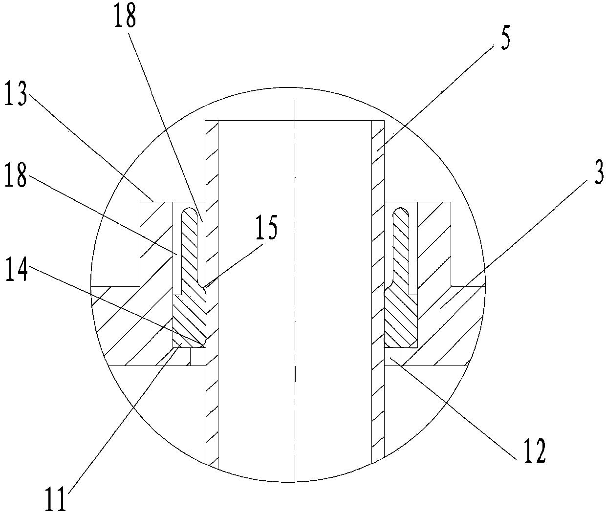
The copper tubes of traditional finned tube heat exchangers are generally thin-walled copper tubes of 0.35-0.50 mm, and the tube sheets are sheet metal parts of 1.5-2 mm. When the copper tubes and tube sheets are welded, traditional welding methods cannot Ensure that the brazing material is evenly filled on the circumference of the copper tube (see attached Image 6 )
The solder flow and solder filling during brazing are affected by the concentricity of the copper tube and the tube sheet, and the consistency is poor. The fillability of the weld cannot be measured, the quality of the weld cannot be judged, and the reliability and fatigue life of the weld cannot be evaluated. The service life of the tube cannot be guaranteed. When the product is working under high-frequency vibration or the tube is inflated for air tightness test, the contact part between the copper tube and the tube sheet will be squeezed due to the small area, causing deformation and leakage of the copper tube. , so it is necessary to improve

Method used


Image

  • Fin tube type heat exchanger
  • Fin tube type heat exchanger
  • Fin tube type heat exchanger

Examples


Embodiment Construction

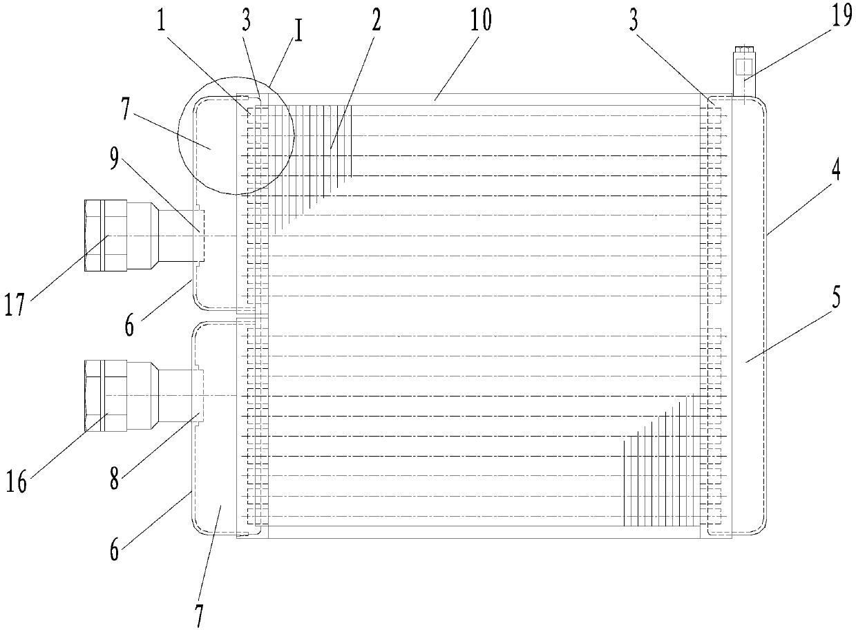
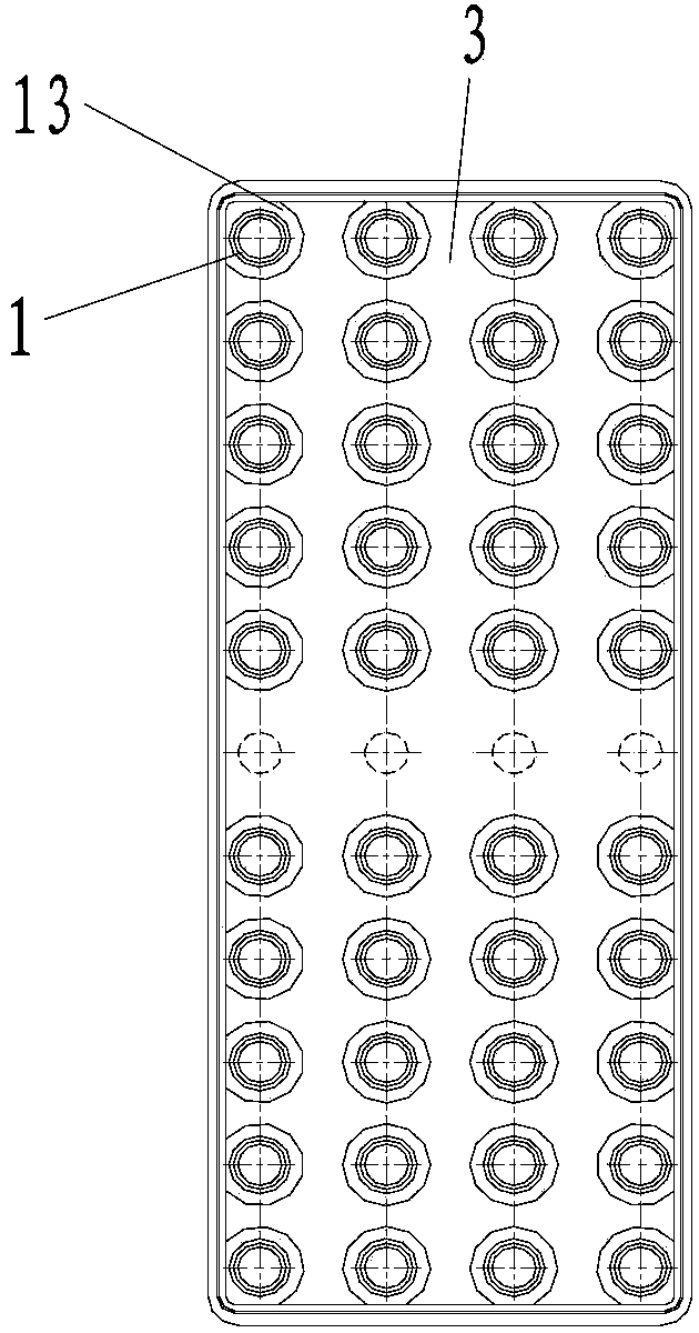
[0020] Attached below Figure 1-5 An embodiment of the present invention is described.

[0021] The finned tube heat exchanger includes a heat exchange tube 1 and a heat dissipation fin 2 on it. The fin 2 is closely matched with the outer diameter of the heat exchange tube 1 to ensure the heat transfer effect. The heat exchange tube 1 is preferably a copper tube. It also includes tube sheets 3, large end caps 4, and small end caps 6 respectively located at both ends of the fins 2, and oil storage chambers I5 and The oil storage chamber II7, wherein the small end cover 6 is provided with a liquid inlet 16 and a liquid outlet 17, specifically, the large end cover 4 and the tube plate 3 are welded together to form an oil storage chamber I5, and the small end cover 6 is formed by a small The end cap A and the small end cap B are composed of the small end cap A and the small end cap B, which are welded together with the tube sheet 3 to form two independent oil storage chambers II7...


PUM


Abstract

The invention provides a fin tube type heat exchanger, which comprises heat exchange tubes, fins, tube plates, a larger end cover and small end covers, wherein the fins are closely contacted with the heat exchange tubes; the tube plates and the large and small end covers are respectively positioned at the two end parts of the fins; an oil storage cavity I and oil storage cavities II are respectively formed between the large and small end covers and the two tube plates; a liquid inlet and a liquid outlet are arranged in the small end covers; stepped holes are manufactured in the tube plates; the heat exchange tubes are inserted into the stepped holes and are in clearance fit with small hole ends of the stepped holes; copper sleeves are arranged in large hole ends of the stepped holes; the thicknesses of the lower end parts of the copper sleeves are greater than the thicknesses of the upper end parts of the copper sleeves; the lower ends of the copper sleeves are closely propped against steps at the bottoms of the large hole ends of the stepped holes to position the copper sleeves; and clearances for braze welding materials to flow into are reserved between the upper end parts of the copper sleeves and the heat exchange tubes as well as between the tube plates and the heat exchange tubes. The fin tube type heat exchanger has the advantages that the evenness of the welding clearances is guaranteed when the copper tubes are welded with the tube plates, the welding materials are fully filled, the welding strength is greatly increased, and meanwhile, working products cannot leak or have other defects in a high-frequency vibration environment.

Description

technical field [0001] The invention belongs to the technical field of heat exchange equipment, and in particular relates to a finned tube heat exchanger. Background technique [0002] Conventional fin-tube heat exchangers are mostly used in static state and normal temperature working environment, but in high-temperature, high-frequency vibration working environments, the reliability requirements of products are higher, and conventional fin-tube heat exchangers are difficult to meet such requirements . The copper tubes of traditional finned tube heat exchangers are generally thin-walled copper tubes of 0.35-0.50 mm, and the tube sheets are sheet metal parts of 1.5-2 mm. When the copper tubes and tube sheets are welded, traditional welding methods cannot Ensure that the brazing material is evenly filled on the circumference of the copper tube (see attached Figure 6 ). The solder flow and solder filling during brazing are affected by the concentricity of the copper tube and...

Claims


Application Information

Patent Timeline
Patent Type & Authority Patents(China)
IPC IPC(8): F28D7/00F28F9/02B23K35/14
Inventor 付积平杨璟宁丽红王孟林黄顺银
Owner SHAANXI BAOCHENG AVIATION INSTR
Learn More