

Experimental device for condensation heat-exchange of steam containing multi-component non-condensable gases
A steam condensation and multi-component technology, applied in the direction of material thermal development, etc., can solve the problems that cannot be experimentally studied, cannot be stabilized, and verified, and achieve the effect of quick and easy calculation and improved operability
- Summary
- Abstract
- Description
- Claims
- Application Information
AI Technical Summary
Problems solved by technology
Method used
Image

Examples
Embodiment Construction
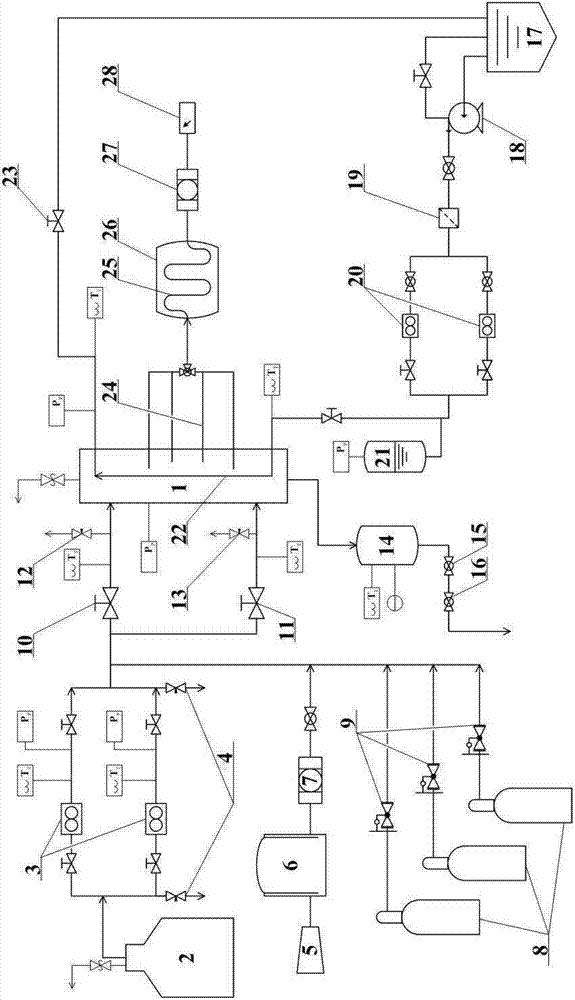
[0060] Below in conjunction with accompanying drawing, the present invention is described in further detail:
[0061] It is mainly composed of steam supply system, air supply system, other gas supply system, cooling water system, condensation experiment body 1, measurement system and data acquisition system. The steam supply system is mainly composed of a boiler 2 and a flow meter 3. The steam is generated by the boiler 2 and flows through the steam flow meter 3 to enter the main line. The air supply system is mainly composed of an air compressor 5, an air storage tank 6, and an oil-air separator 7. The air compressor 5 inflates the air storage tank 6, and the air enters the main line through the oil-air separator 7. Other gas supply systems are mainly composed of a high-pressure gas storage cylinder 8 and a pressure reducing valve 9. The gas is provided by the high-pressure gas storage cylinder 8 and enters the main line through the pressure reducing valve 9. After each gas ...
PUM
 Abstract
Description
Claims
Application Information