Coil panel and assembling method of coil panel and coil panel support and electromagnetic range

An assembly method and a coil disk technology, which are applied in the field of electromagnetic cookers, can solve the problems of harmful smell of glue, affecting the heat dissipation of coil windings, increasing the length and area of ​​coil windings, etc., and achieve the effects of avoiding electrical interference, increasing thermal efficiency, and improving thermal efficiency

Inactive Publication Date: 2013-04-10
BSH ELECTRICAL APPLIANCES JIANGSU
View PDF7 Cites 6 Cited by
  • Summary
  • Abstract
  • Description
  • Claims
  • Application Information

AI Technical Summary

Problems solved by technology

In order to obtain greater power, it is often necessary to increase the length and area of ​​the coil winding, which is not conducive to the miniaturization of the induction cooker
[0004] In addition, the traditional coil winding is usually pasted in the winding groove on the surface of the winding bracket by glue, and the high temperature generated during work will cause the glue used for pasting to produce harmful smell, which is not conducive to human health
And because the glue is attached to the outer layer of the entire coil winding, it will seriously affect the heat dissipation of the coil winding

Method used


Image

  • Coil panel and assembling method of coil panel and coil panel support and electromagnetic range
  • Coil panel and assembling method of coil panel and coil panel support and electromagnetic range
  • Coil panel and assembling method of coil panel and coil panel support and electromagnetic range

Examples


no. 1 example

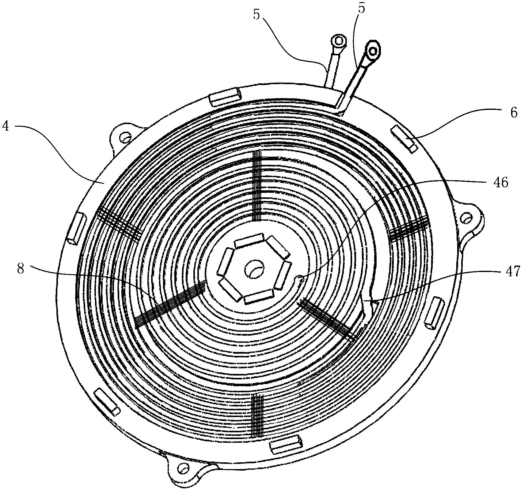
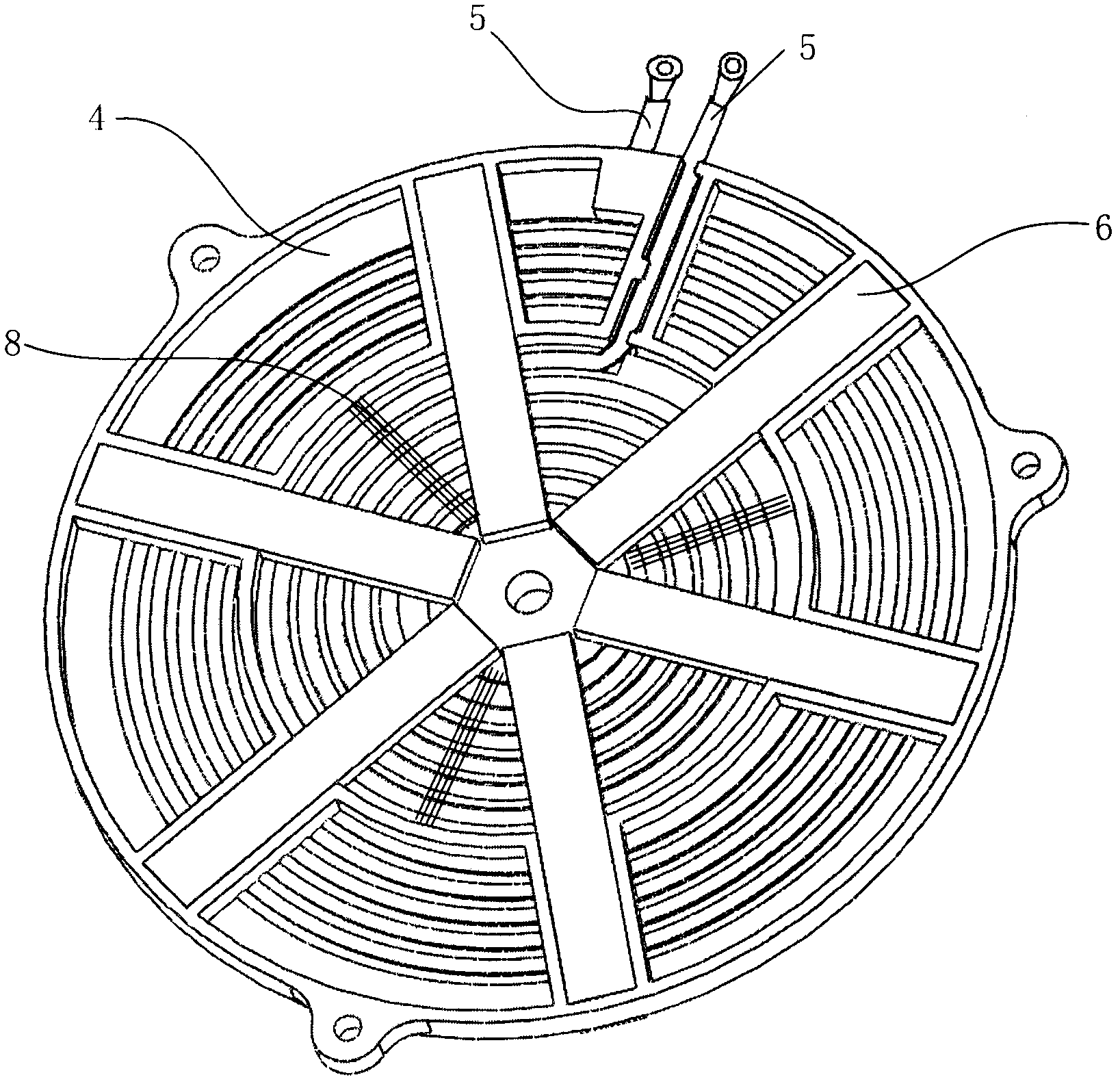
[0058] The double-layer electromagnetic cooker coil disk provided by the first embodiment of the present invention, such as Figure 1 to Figure 2As shown, it is generally composed of a coil disk support 4, a coil 5, a magnetic strip 6, and the like. The coil disc support has a first surface ( figure 1 The upper surface in the application, also referred to as the upper surface) and the second surface ( figure 2 The surface where the magnetic strip 6 is located is also referred to as the lower surface in this application), and the coil 5 is coiled on the first surface and the second surface of the coil disk support 4 . Because the coil 5 is wound on the two surfaces of the coil disc support 4, compared with the existing single-layer coil structure, the length of the coil 5 in the same area is doubled, and accordingly, the thermal efficiency of the coil disc and the electromagnetic range using the coil disc will increase substantially. In addition, since the coils 5 on the up...

no. 2 example

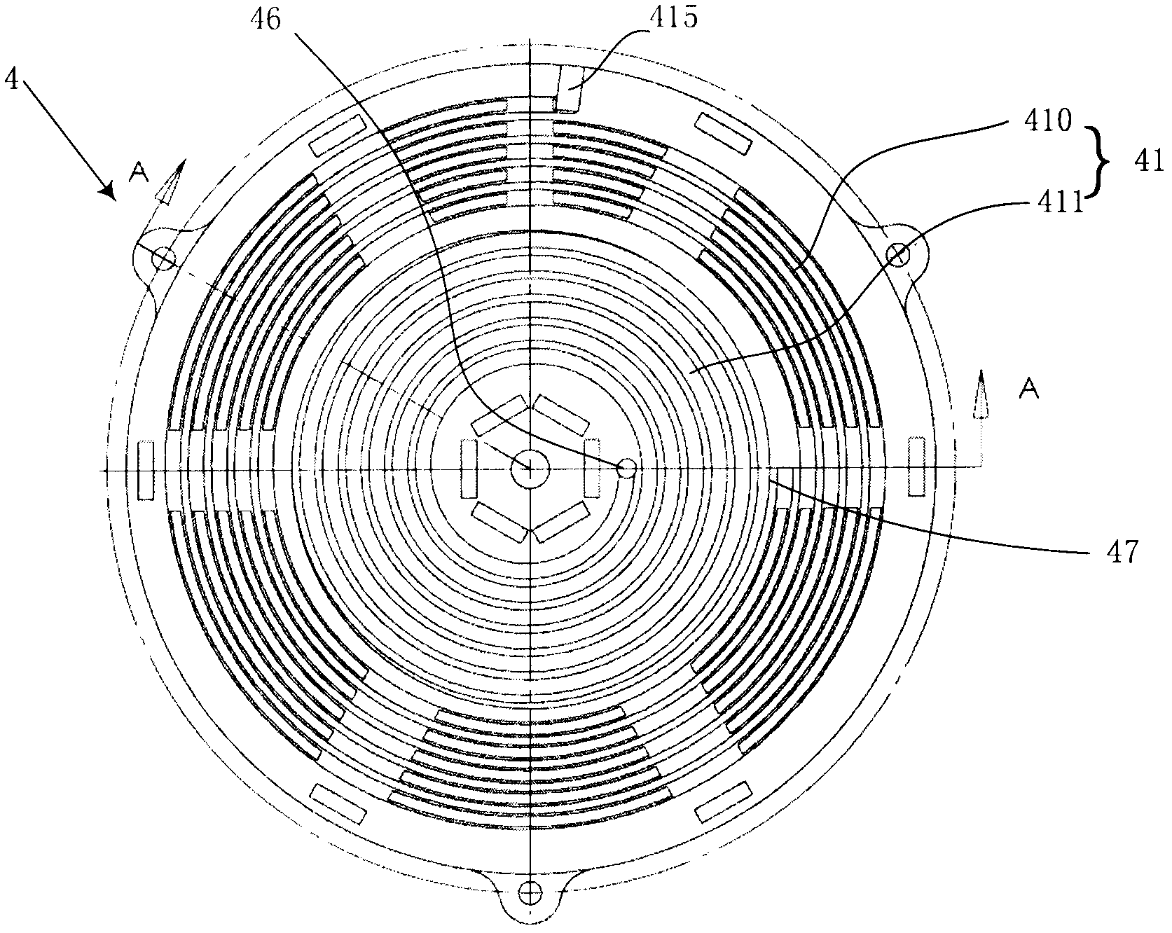
[0069] The coil disk provided by the second embodiment of the present invention, such as Figure 7 to Figure 12 shown. The structure of the coil plate of the second embodiment is substantially the same as that of the first embodiment, the main difference is that the second embodiment uses alternating slots 70 or 75 to replace the coil via holes 46 in the first embodiment, as the channel between the first surface and the second surface . For the convenience of description, the names and reference numerals of the first embodiment will be used here for the same or substantially the same structures, and will not be described in detail in the specification.

[0070] Alternating slots 70 or 75 penetrate the first surface and the second surface of the coil disk support 4 to communicate with the coil slots (including the outer coil slot 410, the inner coil slot 411 and the second coil slot 42) located on the first and second surfaces, It facilitates the winding of subsequent coils. ...


PUM


Abstract

The invention provides a coil panel which comprises a coil panel support (4) and a coil (5), wherein the coil panel support (4) is provided with a first surface and a second surface which are arranged in a back-to-back mode, and the coil (5) is wound around the first surface and the second surface of the coil panel support. The invention further provides an assembling method of the coil panel, the coil panel support and an electromagnetic range. Due to the fact that the coil is wound around the two surfaces of the coil panel support, the length of the coil is doubled in the same area, and correspondingly, the thermal efficiency of the coil panel and the thermal efficiency of the electromagnetic range provided with the coil panel can be improved substantially. Besides, due to the fact that the coil portion on the upper surface and the coil portion on the lower surface are separated by the coil panel support, not only can thermal interference between the coil portion on the upper surface and the coil portion on the lower surface be avoided, but also electric interference between the coil portion on the upper surface and the coil portion on the lower surface can be avoided.

Description

technical field [0001] The invention relates to the field of electromagnetic cookers, in particular to an electromagnetic coil disk and a coil disk support for the electromagnetic cooker. Background technique [0002] The coil plate is a key component of the induction cooker, which largely determines the thermal efficiency of the induction cooker. At present, the common coil reels include winding brackets, magnetic strips and coil windings. There are winding slots on the upper surface of the winding brackets. The coil windings are wound in the winding slots on the upper surface of the winding brackets. The magnetic strips are radial. Distributed on the lower surface of the winding bracket. During specific installation, the magnetic strip can be pasted on the lower surface of the winding bracket, or a card slot can be arranged on the lower surface of the winding bracket, and the magnetic strip is clamped in the slot. For more technical details, please refer to the Chinese u...

Claims


Application Information

Patent Timeline
IPC IPC(8): H05B6/36F24C7/06F24C7/00
Inventor 黄国庆吴辛
Owner BSH ELECTRICAL APPLIANCES JIANGSU
Why Eureka
Try Eureka