
Miniature heatproof moisture-proof welder

A welding machine and miniature technology, applied in welding equipment, arc welding equipment, cooling/ventilation/heating transformation, etc., can solve the problems of large heating value of winding, poor heat dissipation, short circuit of component pins or wiring, etc. The effects of dust accumulation on circuit boards, enhanced external ventilation and cooling, and reduced weight and volume

Inactive Publication Date: 2013-04-17
XINJIANG MENHU INVESTMENT MANAGEMENT
View PDF9 Cites 3 Cited by
  • Summary
  • Abstract
  • Description
  • Claims
  • Application Information

AI Technical Summary

Problems solved by technology

[0003] Electric welding machines have a wide range of applications. Traditional electric welding machine technologies include electromagnetic conversion arc welding machines, later thyristor DC electric welding machines, and more advanced inverter welding machines. Although traditional welding machines have a simple structure, they are bulky, heavy, and power-hungry. High, easy to generate heat, and cannot maintain continuous work. Compared with traditional welding machines, the inverter welding machine has a lighter body weight, but due to the large number of electronic components, complex structure, and high failure rate, the promotion and popularization are hindered.
[0004] The traditional welding machine actually works in a short-circuit state, and the winding itself generates a lot of heat. When the temperature between the turns of the short-circuit operation exceeds the limit temperature of the enameled wire, which is 105°C, a short-circuit burn-in failure will occur between the turns of the wire, resulting in the equipment not being able to continue to work for a long time. ;
[0005] For the inverter welding machine, in addition to the large number of electronic components and complex structure, the high-power components on the power supply board adopt enlarged heat dissipation surface, and the fan is forced to ventilate and dissipate heat to ensure that the working environment temperature is maintained below 85°C. There are limitations in the manufacture of electronic components themselves, and the relevant electronic components are all connected in parallel with dozens of electronic power tubes to achieve different power standards for welding machine calibration. Each high-power tube uses a screw Fastened to the radiator, therefore, as long as the fixing screw of one of the tubes is loose, it will cause poor heat dissipation, and then cause other high-power tubes to overload, heat up and break down, so that the whole welding machine will be burned
[0006] Similarly, due to the complexity of the electronic circuit, the excessive precision of the electronic circuit, and the reliance on a large number of high-power tubes, the large amount of heat generated under the impact of the strong welding current is forced to be cooled by the fan only, and in order to pursue the air-cooled The cooling effect can only be achieved by appropriately enlarging the air duct to keep it unblocked, and not installing filtering devices as much as possible. At the same time, the heating components are directly exposed to the air duct. Usually, the environmental conditions of welding construction are relatively harsh, and the circulating cooling air will inevitably entrain dust and quickly Attached to components such as power tubes or circuit boards, when the air is humid, it will cause short circuits and breakdowns between component pins or wiring. The important thing is that such frequent failures are often misjudged as electronic components Normal loss, which leads to confusion and misunderstandings that cannot further improve the understanding of the performance of the welding machine, and the method of reminding users to pay attention to cleaning the dust in the welding machine is marked on the eye-catching place of the equipment. The seriousness of the above problems cannot be cured by taking remedial measures from the perspective of the equipment structure.

Method used


Image

  • Miniature heatproof moisture-proof welder

Examples


Embodiment Construction

[0014] It will be further described below in conjunction with the drawings and embodiments.

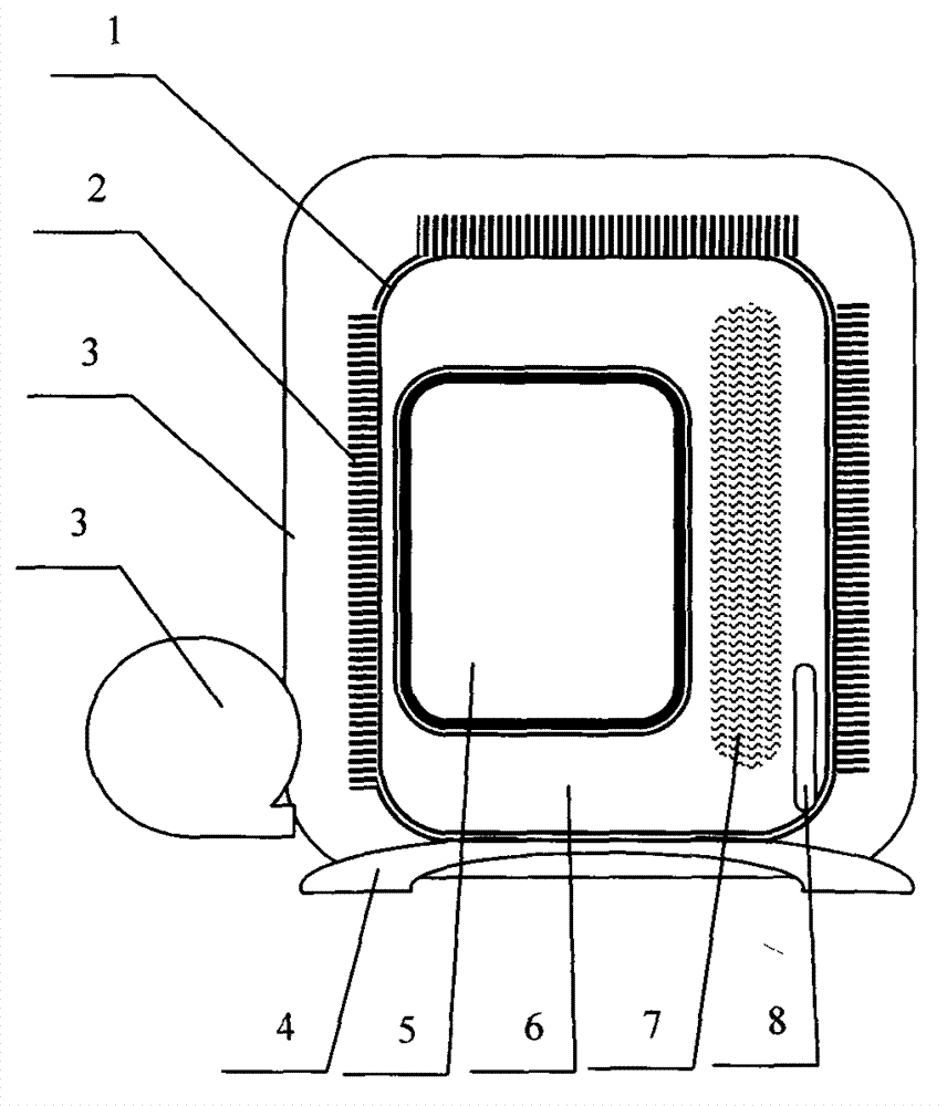
[0015] As attached figure 1 As shown, the welding machine core 6 is installed in the radiator 1, and at the same time, a sealed cavity 7 is formed in the inner gap of the installed core 6, and the thermally conductive insulating oil 8 is injected into the sealed cavity 7, and the radiator 1 is installed in the casing 3. Inside, at the same time, a fan 4 is connected to the casing 3, and the air outlet of the fan 4 is connected to the channel formed by the radiator 1 and the outer wall and the inner wall of the casing 3.

[0016] In the foregoing, the heat sink 1 has heat dissipation fins 2 on the outer wall or the inner wall. The heat sink 1 is made of aluminum and has good thermal conductivity.

[0017] In the foregoing, a temperature sensor 9 is installed in the radiator 1, and the fan 4 starts and stops according to the actual measurement value of the temperature sensor 9 and the preset...


PUM


Abstract

A miniature heatproof moisture-proof welder is characterized in that a welder core (6) is mounted in a radiator (1), a seal cavity (7) is formed on the inner side of the mounted welder core (6) in a clearance manner, heat-conducting insulation oil (8) is injected into the seal cavity (7), the radiator (1) is mounted in an enclosure (3), a fan (4) is connected on the enclosure (3), and an air outlet of the fan (4) is connected into a passage formed by the outer wall of the radiator (1) and the inner wall of the enclosure (3).

Description

Technical field [0001] The present invention relates to a B23K welding technology or device, especially a miniature heat-proof and moisture-proof welding machine. Background technique [0002] The electric welding machine uses the high temperature arc generated when the positive and negative poles are short-circuited instantaneously to melt the solder and the material to be welded on the electrode to achieve the purpose of combining them. The structure is very simple. It is a high-power transformer. Generally, electric welding machines can be divided into two types according to the type of output power. One is AC power and the other is DC. It is made by using the principle of inductance. The inductance will produce huge voltage changes when it is switched on and off. The high voltage arc generated by the instantaneous short circuit of the positive and negative poles is used to melt the solder on the electrode to achieve their union. the goal of. [0003] Electric welding machines...

Claims


Application Information

Patent Timeline
Patent Type & Authority Applications(China)
IPC IPC(8): B23K9/00H05K7/20
Inventor 曹战杰
Owner XINJIANG MENHU INVESTMENT MANAGEMENT
Learn More