
Double-column hydraulic automobile elevator free of balancing of steel wire rope

A wire rope and lift technology, which is applied in the field of double-column hydraulic car lifts, can solve the problems of increased system cost, lifting imbalance, and hydraulic cylinder time difference, and achieve high synchronization stability, less maintenance, and simple structure. Effect

Inactive Publication Date: 2013-04-17
洪寅生
View PDF0 Cites 13 Cited by
  • Summary
  • Abstract
  • Description
  • Claims
  • Application Information

AI Technical Summary

Problems solved by technology

[0003] In the existing double-column hydraulic car lift, lifting devices are usually installed in the left and right columns and connected by hydraulic hoses. One of its shortcomings is that there is a time difference between the left and right hydraulic cylinders when they start lifting. This will lead to lifting imbalance due to the different lifting speeds on the left and right sides. For this reason, the existing lift has added a wire rope synchronization system on the basis of the hydraulic lift.
The wire rope synchronization system has been widely used by similar lifts on the market, but the wire rope is easy to break and wear, and the parts in the system need a lot of maintenance. The riveting of the wire rope is easy to break, which can cause a sudden loss of pressure or Pressurization, so that the unbroken steel wire rope has to bear the danger of the full weight of the load and the impact force, and the hydraulic system is prone to overpressure hazards, causing bursts
The metal nature of the wire rope itself determines its ductility, so the wire rope is easy to extend. During use, it needs to be adjusted frequently, or a mechanical or electrical detection mechanism for the wire rope needs to be added, resulting in an increase in system cost.

Method used


Image

  • Double-column hydraulic automobile elevator free of balancing of steel wire rope
  • Double-column hydraulic automobile elevator free of balancing of steel wire rope
  • Double-column hydraulic automobile elevator free of balancing of steel wire rope

Examples


Embodiment 1

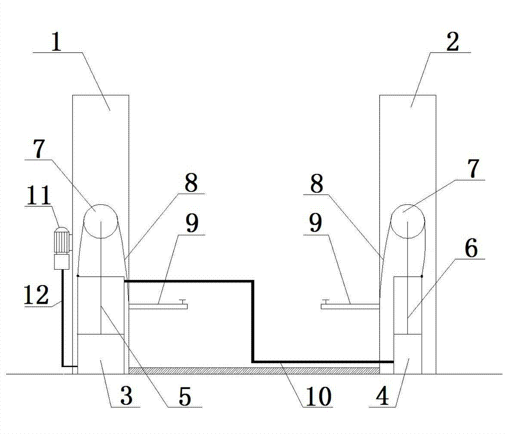
[0022] Embodiment one: if figure 1 Shown is a schematic diagram of the structure of a double-column hydraulic car lift without wire rope adjustment using a sprocket cylinder. The main body of the lift is the main column 1 and the auxiliary column 2 arranged on both sides. A double-acting main cylinder 3 and a single-acting auxiliary cylinder 4 are fixedly installed on the bottom of the auxiliary column 2, both cylinders are set forward, the rodless cavity of the main cylinder 3 communicates with the pump station 11 through the oil pipe 12, and the main cylinder 3 The rod chamber and the rodless chamber of the auxiliary oil cylinder 4 are connected in series through the oil pipe 10; a rotatable sprocket 7 is symmetrically arranged on the top of the piston rod 5 and the piston rod 6, and a chain 8 is arranged on the sprocket 7, and the chain 8 One end is fixed with the cylinder barrel of the oil cylinder, and its other end is fixed with the bracket 9, wherein the bracket 9 slide...

Embodiment 2

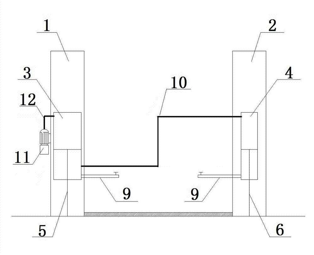
[0025] Embodiment two: if figure 2 Shown is a schematic diagram of the structure of the double-column hydraulic car lift without wire rope adjustment using an inverted oil cylinder. The main body of the lift is the main column 1 and the auxiliary column 2 arranged on both sides. The bottom of column 2 is fixed with double-acting main oil cylinder 3 and single-acting auxiliary oil cylinder 4. Both oil cylinders are inverted. It is fixed with the bottom plate of the auxiliary column 2; the bracket 9 is fixedly installed on the cylinder barrel of the main oil cylinder 3 and the cylinder barrel of the auxiliary oil cylinder 4 respectively, and the bracket 9 can lift up and down with the cylinder barrel; the main oil cylinder 3 The rodless chamber communicates with the pumping station 11 through an oil pipe 12 , and the rodless chamber of the main oil cylinder 3 and the rodless chamber of the auxiliary oil cylinder 4 are connected in series through an oil pipe 10 .

[0026] The i...

Embodiment 3

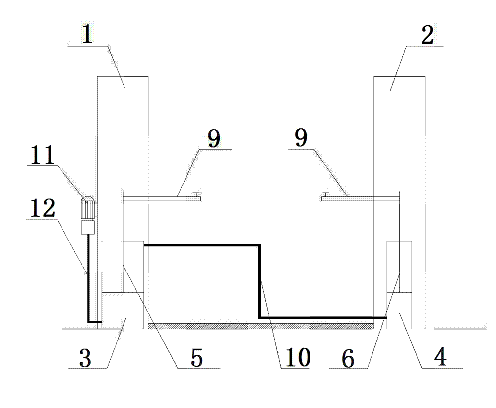
[0028] Embodiment three: as image 3 Shown is a schematic diagram of the structure of a double-column hydraulic car lift without wire rope adjustment using a straight-top oil cylinder. The main body of the lift is the main column 1 and the auxiliary column 2 arranged on both sides. A double-acting main cylinder 3 and a single-acting auxiliary cylinder 4 are fixedly installed on the bottom of the auxiliary column 2, both cylinders are set forward, the rodless cavity of the main cylinder 3 communicates with the pump station 11 through the oil pipe 12, and the main cylinder 3 The rod chamber and the rodless chamber of the auxiliary oil cylinder 4 are connected in series through the oil pipe 10; at the tops of the piston rods 5 and 6 of the main oil cylinder 3 and the auxiliary oil cylinder 4, a bracket 9 is fixedly installed, and the bracket 9 can be connected with the piston rods 5 and 6. Up and down lifting motion.

[0029] The initial state of the piston rod 5 on the main oil...


PUM


Abstract

The invention particularly relates to a double-column hydraulic automobile elevator free of balancing of a steel wire rope. A main oil cylinder and an auxiliary oil cylinder are respectively arranged in stand columns on two sides of the double-column hydraulic automobile elevator, a rod cavity of the main oil cylinder is serially connected with a rodless cavity of the auxiliary oil cylinder via an oil pipe, and sectional area of the rod cavity of the main oil cylinder is equal to that of the rodless cavity of the auxiliary oil cylinder. According to the principle of isometric oil cylinder synchronization, the main oil cylinder and the auxiliary oil cylinder are set in at least four modes specifically including chain wheel mode, inverting mode, direct pushing mode and inverse pulling mode. The double-column hydraulic automobile elevator free of balancing of the steel wire rope has the advantage that support arms on the two sides can be kept to be lifted up synchronously so as to avoid various safety and maintenance problems caused by a steel wire rope synchronizing system utilized by the existing double-column hydraulic automobile elevator, and is simple in structure, low in cost, high in synchronizing stability, and few in required maintenance in a later period.

Description

technical field [0001] The invention relates to a car lift, in particular to a double-column hydraulic car lift without steel wire ropes for balancing. Background technique [0002] A car lift is a device used to support a certain part of the car chassis or body to lift the car. As a member of the car lift family, the hydraulic car lift has advantages unmatched by other lifts, such as its wide working range of structure, the ability to repair high-ceiling vehicles, and the open working space. [0003] In the existing double-column hydraulic car lift, lifting devices are usually installed in the left and right columns and connected by hydraulic hoses. One of its shortcomings is that there is a time difference between the left and right hydraulic cylinders when they start lifting. This will cause lifting imbalance due to the different lifting speeds on the left and right sides. For this reason, existing lifts have added a synchronous system of wire ropes on the basis of hydra...

Claims


Application Information

Patent Timeline
IPC IPC(8): B66F7/00
Inventor 洪寅生
Owner 洪寅生
Learn More