
Telescopic handler

A technology for forklifts and forks, applied in motor vehicles, lifting devices, transportation and packaging, etc., can solve the problems of reduced reliability, limited loading and unloading capacity, etc., and achieve long unloading distance, large unloading angle range, and cargo handling operations flexible effects

Active Publication Date: 2013-04-17
XIAMEN XIAJIN MACHINERY
View PDF7 Cites 10 Cited by
  • Summary
  • Abstract
  • Description
  • Claims
  • Application Information

AI Technical Summary

Problems solved by technology

Although this kind of forklift truck has the characteristics of better vision for the driver and relatively stable loading and unloading of goods, this kind of forklift truck can only load and unload goods with smaller volume and lighter weight.
The main reasons are: first, when the volume of the cargo is large, the moving track of the front rocker arm of the working device will interfere with the cargo, limiting the height of loading and unloading cargo; second, the lifting mechanism of the working device is an eight-link structure, although its It improves the handling flexibility, but also limits the lifting weight, and the weight of the goods it can dig up is relatively light; third, although there are three brake calipers evenly distributed along the circumferential direction of the brake disc to improve the braking ability, but when the forklift truck bears When under heavy load, the reliability of the brake will be reduced due to the heating of the brake disc
Therefore, its loading and unloading capabilities are limited

Method used


Image

  • Telescopic handler
  • Telescopic handler
  • Telescopic handler

Examples


Embodiment Construction

[0033] The present invention will be described in further detail below in conjunction with the accompanying drawings and specific embodiments.

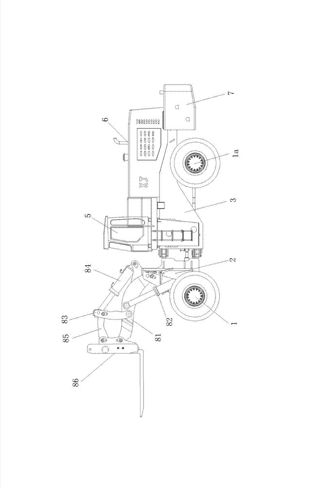
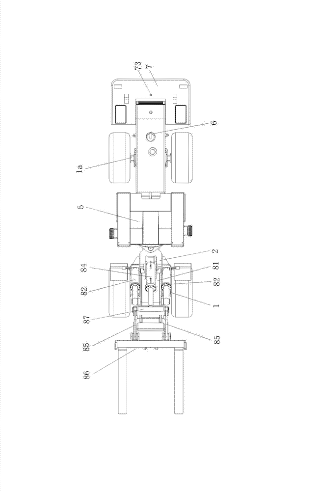
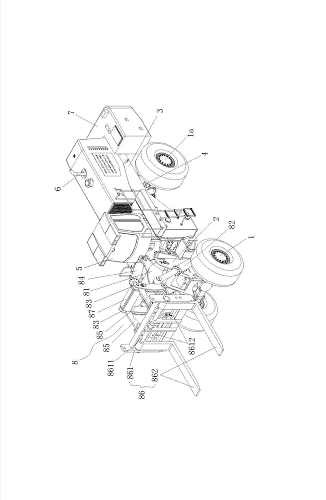
[0034] Figure 1 to Figure 3 As shown, a forklift truck includes front and rear drive axles 1, 1a with tires, front frame 2, rear frame 3, subframe 4, cab 5, engine 6, torque converter, speed changer Box, transmission shaft, balance weight 7, working device 8, the front side of the lower part of the front frame 2 is installed on the front drive axle 1, the lower part of the rear frame 3 is connected to the rear drive axle 1a through the subframe 4, and the cab 5. The engine 6 is installed on the rear frame 3, the engine 6 is connected to the front and rear drive axles 1 and 1a through a torque converter, a gearbox, and a drive shaft, and the balance weight 7 is connected to the rear of the rear frame 3;

[0035] The working device 8 includes a boom 81, two boom cylinders 82, two rocking arms 83, a bucket cylinder 84, two pull rods 85...


PUM


Abstract

The invention discloses a telescopic handler which comprises a front driving axle and a back driving axle which are provided with tires, a front frame, a back frame, an auxiliary frame, a cab, an engine, a counter weight block and a working device. The working device comprises a movable arm, two movable arm oil cylinders, two rocker arms, a rotating bucket oil cylinder, two pull rods and an object fork. The lower end of the movable arm is hinged on the upper portion of the front frame, the upper end of the movable arm is hinged on the back lower portion of the object fork, the lower ends of the two movable arm oil cylinders are respectively hinged on two sides of the lower portion of the front frame, and the upper ends of the two movable arm oil cylinders are hinged on two sides of the middle of the movable arm. The lower ends of the two rocker arms are hinged on two sides of the middle of the movable arm, the lower end of the rotating bucket oil cylinder is hinged on the upper side of the lower portion of the movable arm, the upper end of the rotating bucket oil cylinder is hinged with the upper ends of the two rocker arms through a connection rod, one ends of the two pull rods are hinged at the position of the rocker arms close to the upper end, and the other ends of the two pull rods are respectively hinged on the back upper portion of the object fork. The telescopic handler is capable of forking materials with large size and weight, long in unloading distance, large in unloading angle and flexible to operate.

Description

technical field [0001] The invention relates to the technical field of engineering machinery manufacturing, in particular to a forklift truck. Background technique [0002] In the field of existing construction machinery manufacturing technology, the forklift truck developed from the comprehensive loader and forklift technology has the advantages of large forklift weight and flexible operation, and has been widely used in the fields of stone loading and unloading and container loading and unloading. However, due to the increasing volume of stone mining, the speed requirements for loading and unloading, stacking, retrieving and loading of containers are getting faster and faster, and higher requirements are placed on the loading and unloading capacity of forklift trucks. [0003] On September 26, 2012, an application for an invention patent with the application number 201210190601.4 and the name "a forklift truck" was published, which includes a front frame, a rear frame, a w...

Claims


Application Information

Patent Timeline
Patent Type & Authority Applications(China)
IPC IPC(8): B66F9/06B66F9/075B66F9/12B66F9/22B62D53/00
Inventor 刘宝彦沈光伟
Owner XIAMEN XIAJIN MACHINERY
Learn More